


Bicycle Rear-Light Afterglow Circuit
#bicycle
#rear-light
#dynamo
#safety
#cycling
#UK laws
#afterglow
#LED
#power management
#automotive
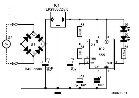
Description: This article is relevant only to readers whose bicycle lights are powered by a dynamo. The regulations regarding bicycle lights in the United Kingdom are stricter than in many other countries, making dynamos a rarity in the UK. For safety reasons, cyclists in the UK are required to have the rear light of their bicycles illuminated even when stationary. This practice is advisable in other countries as well, even if not legally mandated. The ultra-bright LEDs are not directly powered by the regulator, IC1, but instead through a timer, IC2. The timer operates on a pulsating voltage with a duty cycle of 10%, which results in minimal current consumption and allows the reservoir capacitor, C2, to power the LEDs for an extended period. Capacitor C2 is charged while the bicycle is in motion, utilizing the dynamo when it comes into contact with the wheel. This charging occurs through bridge rectifier B1 and low-dropout regulator IC1, which provides a stable output of +5 V. When the bicycle is in use but stationary, such as at traffic lights, the voltage across C2 activates the astable multivibrator (AMV) IC2. With the specified component values, the turn-on time is approximately 0.02 seconds, but the LEDs will not illuminate until 0.25 seconds have passed.
The described circuit utilizes a dynamo to power bicycle lights, integrating a series of components to ensure effective illumination while conserving battery power. The dynamo generates alternating current (AC), which is converted to direct current (DC) through bridge rectifier B1. This component comprises four diodes arranged in a bridge configuration, allowing current to flow in a single direction, thereby charging capacitor C2.
The low-dropout regulator IC1 is essential for maintaining a consistent output voltage of +5 V, regardless of variations in the input voltage generated by the dynamo. This regulated voltage is crucial for the stable operation of the LEDs and the timer circuit. The timer IC2, configured as an astable multivibrator, generates a square wave output that controls the on/off cycling of the LEDs. The duty cycle of 10% means that the LEDs are illuminated for a brief period compared to the time they are off, significantly reducing power consumption.
Capacitor C2 serves as an energy reservoir, storing charge when the bicycle is in motion. When the bicycle comes to a stop, the stored energy in C2 is used to power IC2, which delays the activation of the LEDs for 0.25 seconds after the bicycle is stationary. This feature enhances visibility and safety by ensuring that the rear light remains illuminated even when the cyclist is at a standstill, such as at traffic signals.
In summary, the circuit design effectively combines a dynamo-powered system with intelligent timing and regulation to ensure that bicycle lights operate safely and efficiently, adhering to stringent regulations while promoting cyclist visibility. The careful selection of components and their configuration plays a vital role in achieving the desired functionality and performance of the lighting system.This article is of interest only to readers whose bicycle lights are powered by a dynamo. The laws on bicycle lights in the United Kingdom are stricter than in most other countries and a dynamo is, therefore, a rarity in the UK. For safety`s sake, it is obligatory for cyclists in the UK to have the rear light of their bicycles on even when they ar
e at standstill. Such a rule is, of course, also advisable in other countries, even when it is not mandatory. The super-luminous LEDs are not powered directly by the regulator, IC1, but via a timer, IC2. The timer is driven by a pulsating voltage with a duty factor of 10%. This ensures very low current drain and also that the reservoir capacitor, C2, can energize the LEDs for a long time. Capacitor C2 is charged when the bicycle, and thus the dynamo if this makes contact with the relevant wheel, is ridden.
This happens via bridge rectifier B1, and low-drop regulator IC1. The output of the regulator is a steady +5 V. When the bicycle is in use, but at standstill, for instance, at traffic lights, the potential across C2 powers astable multivibrator (AMV) IC2. With component values as specified, the switch-on time is about 0. 02 s, but the LEDs are not energized until 0. 25 s have elapsed.
The described circuit utilizes a dynamo to power bicycle lights, integrating a series of components to ensure effective illumination while conserving battery power. The dynamo generates alternating current (AC), which is converted to direct current (DC) through bridge rectifier B1. This component comprises four diodes arranged in a bridge configuration, allowing current to flow in a single direction, thereby charging capacitor C2.
The low-dropout regulator IC1 is essential for maintaining a consistent output voltage of +5 V, regardless of variations in the input voltage generated by the dynamo. This regulated voltage is crucial for the stable operation of the LEDs and the timer circuit. The timer IC2, configured as an astable multivibrator, generates a square wave output that controls the on/off cycling of the LEDs. The duty cycle of 10% means that the LEDs are illuminated for a brief period compared to the time they are off, significantly reducing power consumption.
Capacitor C2 serves as an energy reservoir, storing charge when the bicycle is in motion. When the bicycle comes to a stop, the stored energy in C2 is used to power IC2, which delays the activation of the LEDs for 0.25 seconds after the bicycle is stationary. This feature enhances visibility and safety by ensuring that the rear light remains illuminated even when the cyclist is at a standstill, such as at traffic signals.
In summary, the circuit design effectively combines a dynamo-powered system with intelligent timing and regulation to ensure that bicycle lights operate safely and efficiently, adhering to stringent regulations while promoting cyclist visibility. The careful selection of components and their configuration plays a vital role in achieving the desired functionality and performance of the lighting system.This article is of interest only to readers whose bicycle lights are powered by a dynamo. The laws on bicycle lights in the United Kingdom are stricter than in most other countries and a dynamo is, therefore, a rarity in the UK. For safety`s sake, it is obligatory for cyclists in the UK to have the rear light of their bicycles on even when they ar
e at standstill. Such a rule is, of course, also advisable in other countries, even when it is not mandatory. The super-luminous LEDs are not powered directly by the regulator, IC1, but via a timer, IC2. The timer is driven by a pulsating voltage with a duty factor of 10%. This ensures very low current drain and also that the reservoir capacitor, C2, can energize the LEDs for a long time. Capacitor C2 is charged when the bicycle, and thus the dynamo if this makes contact with the relevant wheel, is ridden.
This happens via bridge rectifier B1, and low-drop regulator IC1. The output of the regulator is a steady +5 V. When the bicycle is in use, but at standstill, for instance, at traffic lights, the potential across C2 powers astable multivibrator (AMV) IC2. With component values as specified, the switch-on time is about 0. 02 s, but the LEDs are not energized until 0. 25 s have elapsed.
Using white LEDs
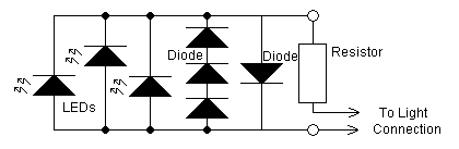
The yellow LEDs are on a small PCB, which are easy to remove. On the PCB there are 3 yellow LEDs and 4 diodes. Pictures of the PCB can be seen here: Top-side - Bottom-side. The schematic is as follows:...
Bicycle tail light flashing
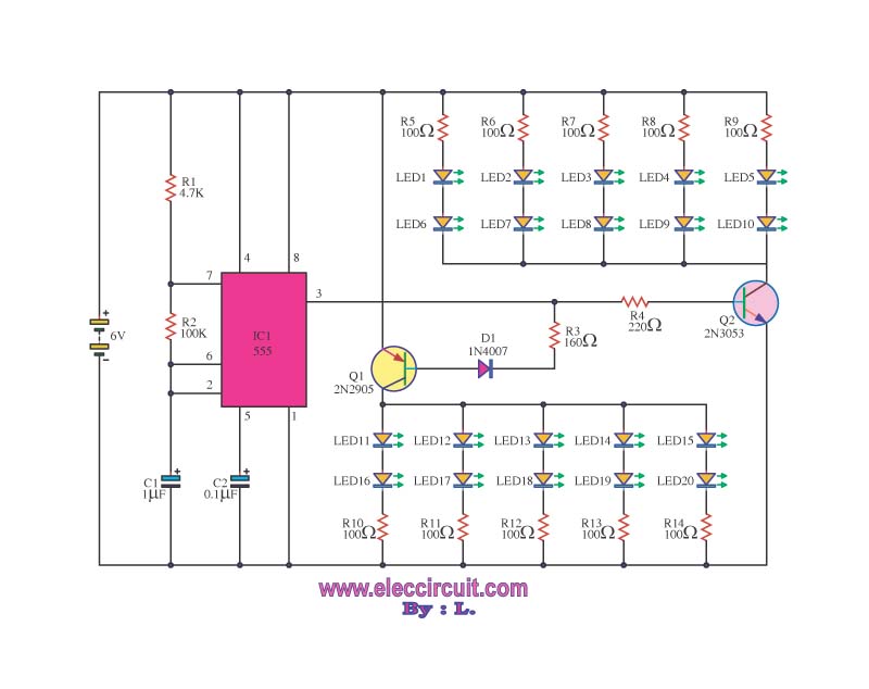
Present roads are in better condition than the former Pan. The traffic flow is convenient; however, high speeds are often observed. When using bicycles at night, safety concerns arise.
The statement highlights the improvement in road conditions compared to previous infrastructure....
White LED Head Lamp
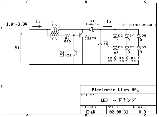
This is a practical white LED head mount lamp (flashlight). Recently many white LED flashlights appear on the market. However, most flashlights require three cells because they are regulating output current with only series resistor. The odd number of cells...
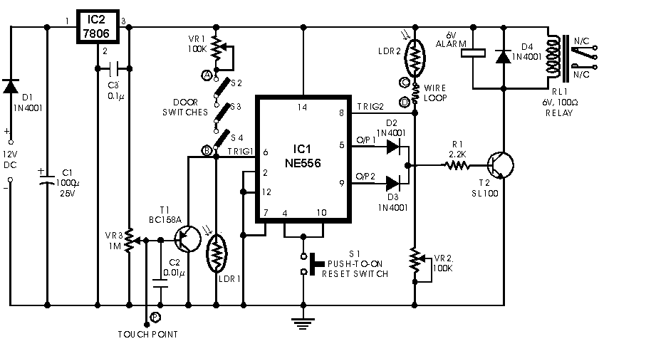
dancing lights circuit diagram
This circuit serves as a decorative element or indicator, featuring adjustable flashing or dancing speeds of LEDs and the ability to create various light patterns. It consists of two astable multivibrators: one formed by transistors T1 and T2, and the...
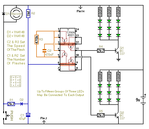
Three Flashing LED Doorbells For The Hearing Impaired
When the push switch is activated, the buzzer sounds, and the LEDs start to flash. For the hearing members of the household, the buzzer functions as a standard doorbell, providing reassurance to the visitor that the doorbell is operational. Upon...
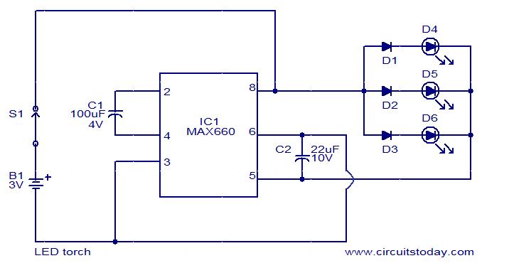
LED torch using MAX660
This is a simple LED torch circuit based on the MAX660 integrated circuit from MAXIM semiconductors. The MAX660 is a CMOS monolithic voltage converter IC capable of driving three bright white LEDs connected in parallel to output pin 8. The...
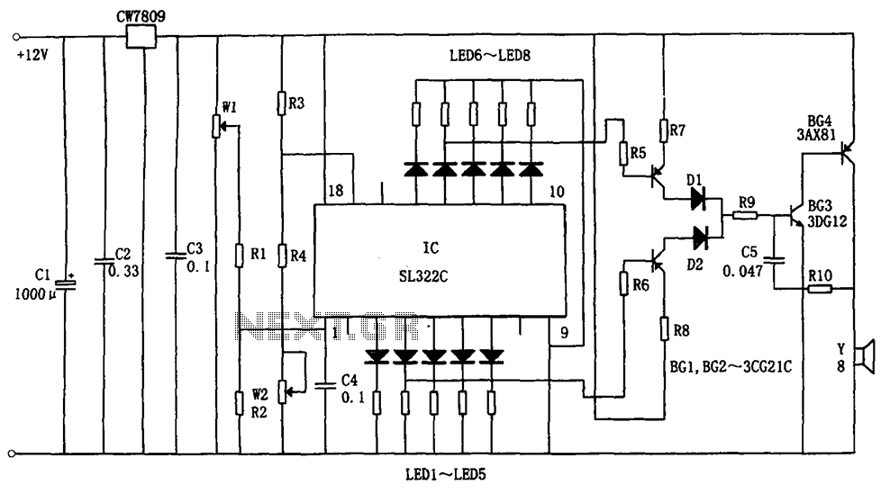
Hydraulic oil Automotive LED Alarm SL322C schematic
The circuit illustrated in the figure is a hydraulic oil level alarm system for automotive applications. It consists of a light-emitting diode (LED) driver, the SL322C integrated circuit (IC), a voltage regulator circuit (CW7809), and hydraulic oil level sensors (W1,...
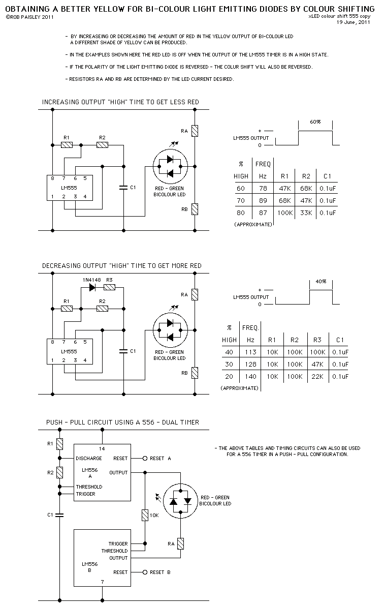
Colour Shifting LED`s
These circuits provide a means of altering the YELLOW output of RED / GREEN type two colour light emitting diodes. These circuits use the LM555 timer chip.
The circuit described utilizes the LM555 timer integrated circuit (IC) to modulate the output...
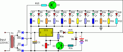
automatic low power emergancy light
An emergency light system utilizing white LEDs, which provides several advantages: 1. It is highly bright due to the use of white LEDs. 2. The light activates automatically during a mains power failure and deactivates when mains power is restored....