


Brightness controller for low power lamps
#NE555
#astable multivibrator
#brightness control
#transistor
#POT
#incandescent lamps
#duty cycle
#low power
#PWM
#light dimmer
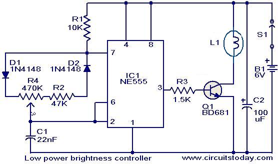
Description: The circuit presented here is designed to control the brightness of low-power incandescent lamps. It utilizes the NE555 integrated circuit, configured as an astable multivibrator with a variable duty cycle. The output from the IC is connected to the base of transistor Q1, which drives the lamp. The duty cycle of the multivibrator can be adjusted by changing the position of potentiometer R4. Consequently, the brightness of the lamp varies in accordance with the setting of potentiometer R4. This circuit can also be adapted for speed control of small DC motors.
The circuit employs the NE555 timer IC, which is a versatile component widely used in various applications. In this configuration, the NE555 operates as an astable multivibrator, generating a continuous square wave output. This output toggles between high and low states, with the duty cycle determining the proportion of time the output remains high. By adjusting the resistance of potentiometer R4, the duty cycle can be varied, which in turn modulates the average voltage applied to the load, resulting in a change in brightness for the incandescent lamp.
Transistor Q1 acts as a switch that controls the current flowing through the lamp. When the output of the NE555 is high, Q1 is turned on, allowing current to flow through the lamp, thus illuminating it. Conversely, when the output is low, Q1 turns off, cutting off the current and extinguishing the lamp. The effective brightness is directly proportional to the duty cycle; a higher duty cycle results in a brighter lamp, while a lower duty cycle leads to dimmer illumination.
This circuit's design can be easily adapted for other applications, such as controlling the speed of small DC motors. In this case, the same principles apply, where the average voltage delivered to the motor is controlled by adjusting the duty cycle of the NE555 output. By varying the duty cycle, the motor speed can be finely tuned, providing a practical solution for applications requiring speed control. Overall, this circuit exemplifies a straightforward yet effective method for managing the brightness of lamps and the speed of motors using minimal components.The circuit given here can be used to control the brightness of low power incandescent lamps. The circuit is based on IC NE555 which is wired as an astable multivibrator with variable duty cycle. The output of IC is connected to the base of transistor Q1. The Q1 drives the lamp. The duty cycle of the multivibrator can be varied by varying the POT R 4. As a result, the brightness of the lamp varies according to the position of the POT R4. The same circuit can be also used for speed control of small DC motors.
The circuit employs the NE555 timer IC, which is a versatile component widely used in various applications. In this configuration, the NE555 operates as an astable multivibrator, generating a continuous square wave output. This output toggles between high and low states, with the duty cycle determining the proportion of time the output remains high. By adjusting the resistance of potentiometer R4, the duty cycle can be varied, which in turn modulates the average voltage applied to the load, resulting in a change in brightness for the incandescent lamp.
Transistor Q1 acts as a switch that controls the current flowing through the lamp. When the output of the NE555 is high, Q1 is turned on, allowing current to flow through the lamp, thus illuminating it. Conversely, when the output is low, Q1 turns off, cutting off the current and extinguishing the lamp. The effective brightness is directly proportional to the duty cycle; a higher duty cycle results in a brighter lamp, while a lower duty cycle leads to dimmer illumination.
This circuit's design can be easily adapted for other applications, such as controlling the speed of small DC motors. In this case, the same principles apply, where the average voltage delivered to the motor is controlled by adjusting the duty cycle of the NE555 output. By varying the duty cycle, the motor speed can be finely tuned, providing a practical solution for applications requiring speed control. Overall, this circuit exemplifies a straightforward yet effective method for managing the brightness of lamps and the speed of motors using minimal components.The circuit given here can be used to control the brightness of low power incandescent lamps. The circuit is based on IC NE555 which is wired as an astable multivibrator with variable duty cycle. The output of IC is connected to the base of transistor Q1. The Q1 drives the lamp. The duty cycle of the multivibrator can be varied by varying the POT R 4. As a result, the brightness of the lamp varies according to the position of the POT R4. The same circuit can be also used for speed control of small DC motors.
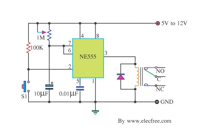
Basic Timer Control with NE555
Many friends take an interest in the circuit involving the highly popular IC 555, which is an integrated circuit. This circuit sets the time in a basic manner.
The IC 555 timer is a versatile and widely utilized component in electronics,...
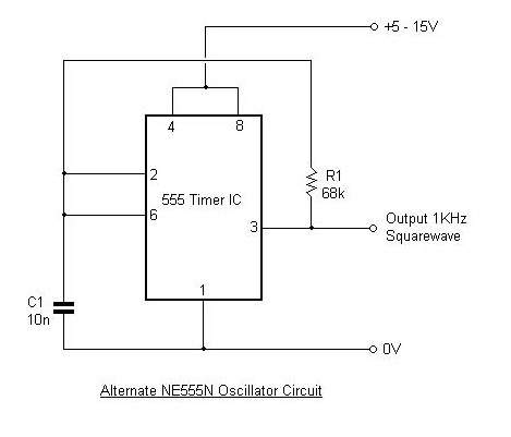
NE555 Timer
This article outlines the design and applications of the NE555 timer. The content is straightforward and informative, providing valuable insights into various components associated with the NE555. Readers can find and purchase these components through the article. It discusses several...
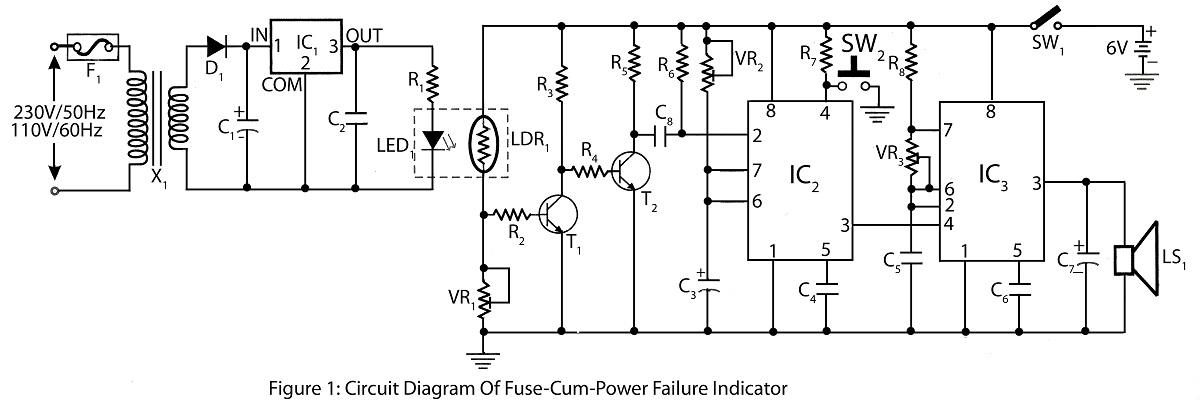
Fuse-Cum-Power Failure Indicator with alarm
The Fuse Cum Power Failure Indicator utilizes a thermistor and a timer IC (NE555) in its circuit design. The circuit diagram includes a parts list for the fuse cum power failure indicator, which signals instances of power failure.
The Fuse Cum...
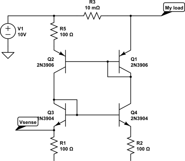
Transistor current mirror circuit
The bases and emitters of the transistors are connected together, resulting in equal base-emitter voltages. Assuming the transistors are identical, equal Vbe leads to equal base currents, which in turn results in equal collector-emitter currents. By adjusting the voltage and...
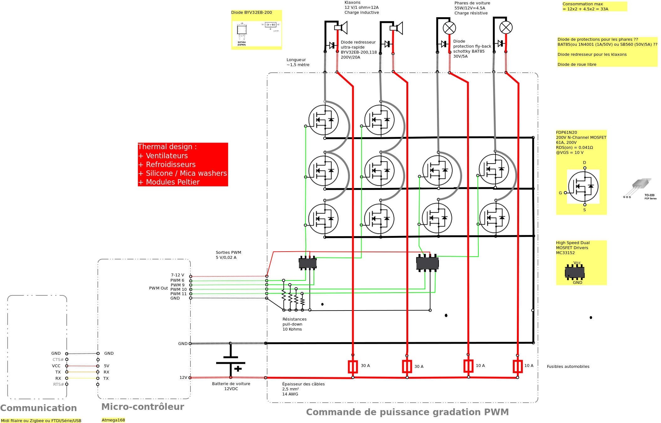
Control car horns in PWM
Past experiences were quite challenging due to the inductive nature of car horns, which require 12A of current, with peak demands reaching 20 to 30A. The current electronic system lacks reliability, given the high intensity. There is a need to...
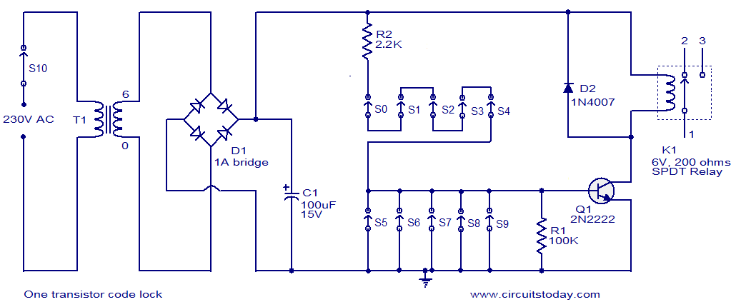
One 2N2222 Transistor Code Lock
The circuit consists of a basic transistor switch with a relay connected at its collector as the load. This represents a straightforward electronic code lock circuit that employs a single transistor.
The circuit operates by utilizing a transistor as a switch...
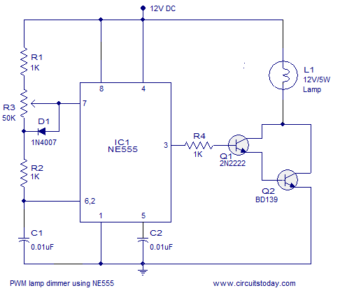
PWM lamp dimmer using NE555 timer IC. Complete circuit diagram and working
A simple PWM lamp dimmer using the NE555 timer IC. The 555 timer IC is configured as a variable duty cycle astable multivibrator to control the brightness of the lamp.
The described circuit utilizes the NE555 timer IC, a versatile and...

Kapanadze 5
The emitter voltage drops completely to 0V from 42V during the pulse when the transistor is conducting or saturated. This contrasts with a pure resistive load (the 4.7 Ohm resistor mentioned in the previous video), where the collector-emitter voltage does...
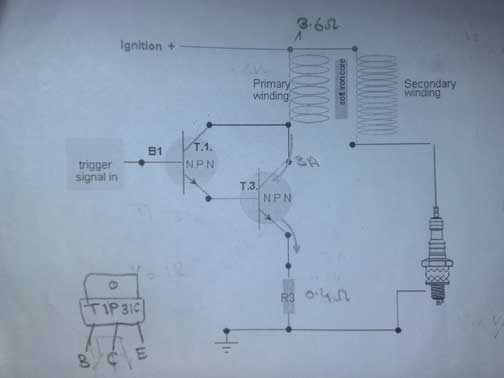
transistor ignition shematic 3
A request for assistance has been made regarding the development of a transistor ignition system to replace the point breaker in a motorcycle. The individual has researched extensively online but has not found a simple and effective circuit. The available...