


Christmas lights consisting of a circuit diagram of optocoupler
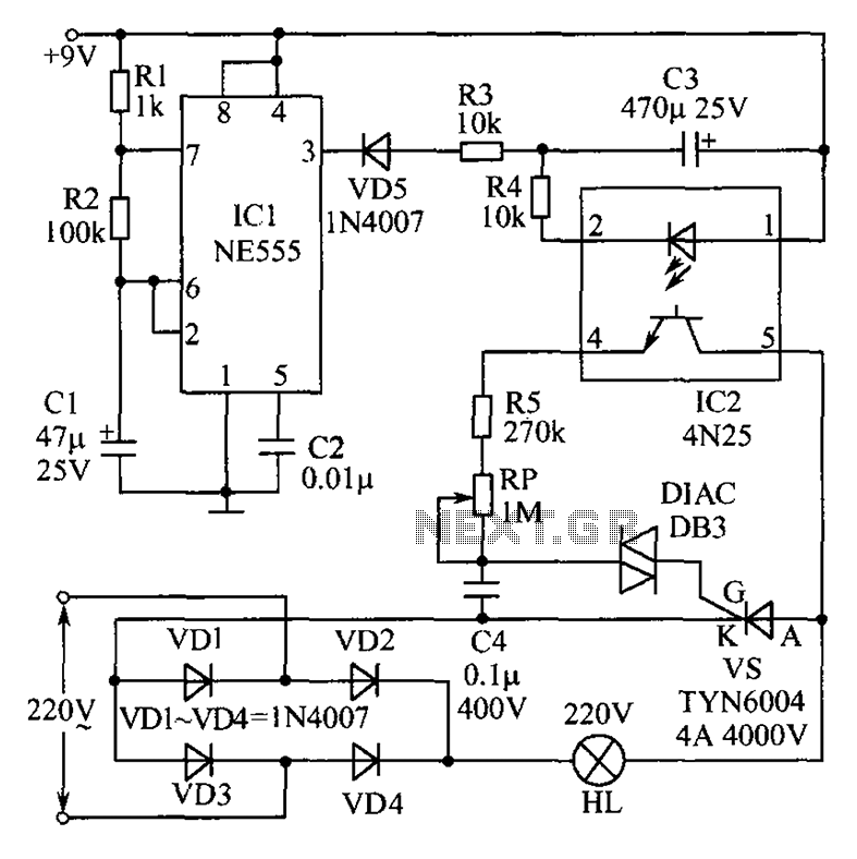
Description: This circuit features an appealing Christmas lights setup. Upon activation, the lights (HL) gradually increase in brightness. Once they reach maximum brightness, they automatically dim, and upon reaching the lowest brightness, they gradually brighten again, creating a smooth transition throughout the entire process. The change in brightness is influenced by the discharge of capacitor C3. When the output of IC1 (NE555) pin 3 is high, capacitor C3 discharges through IC2 (CN25) optical isolation, causing the brightness of lantern HL to begin to decrease. IC1 is configured as a non-stable oscillator, with its frequency determined by resistors R1, R2, and capacitor C1.
The described Christmas lights circuit utilizes an NE555 timer integrated circuit (IC1) configured in a non-stable mode to create a continuous oscillation that controls the brightness of the lights (HL). The circuit's operation begins when power is applied, allowing the timer to generate a square wave output. The frequency of this oscillation is determined by the values of resistors R1 and R2, along with capacitor C1, which set the timing intervals for the charging and discharging cycles.
As the output from pin 3 of the NE555 goes high, capacitor C3, which is connected to the circuit, begins to discharge through the optical isolator IC2 (CN25). This discharge process causes the brightness of the lights (HL) to decrease gradually. The optical isolator serves as a safety mechanism, ensuring that the high voltage present in the lighting circuit does not affect the low voltage control circuit.
Once the lights reach their minimum brightness, the NE555 timer output transitions low, allowing capacitor C3 to recharge. This recharging phase enables the lights to gradually brighten again, completing the cycle. The smooth transitions between bright and dim states create an aesthetically pleasing effect, ideal for festive decorations. The entire circuit is designed to provide a visually appealing illumination effect while ensuring reliable operation through the use of standard electronic components.
In summary, this Christmas lights circuit is an excellent example of utilizing basic electronic components to achieve a dynamic lighting effect, making it suitable for various decorative applications during the holiday season. As shown is a very attractive Christmas lights circuit. When the power is turned on, lights HL will gradually become brighter; when it reaches the brightest, it will automatica lly gradually darken; et brightness of the darkest time, will automatically brighten gradually, so repeated. Smooth the entire change process. Brightness change process depends on the charger lights HL capacitor C3 discharges. When IC1 (NE555) 3-pin output is high, the capacitor C3 begins to discharge through the IC2 (CN25) optical isolation, lantern HL brightness began to decline.
IC1 here set no stable oscillator whose frequency is determined by R1, R2 and C1.
The described Christmas lights circuit utilizes an NE555 timer integrated circuit (IC1) configured in a non-stable mode to create a continuous oscillation that controls the brightness of the lights (HL). The circuit's operation begins when power is applied, allowing the timer to generate a square wave output. The frequency of this oscillation is determined by the values of resistors R1 and R2, along with capacitor C1, which set the timing intervals for the charging and discharging cycles.
As the output from pin 3 of the NE555 goes high, capacitor C3, which is connected to the circuit, begins to discharge through the optical isolator IC2 (CN25). This discharge process causes the brightness of the lights (HL) to decrease gradually. The optical isolator serves as a safety mechanism, ensuring that the high voltage present in the lighting circuit does not affect the low voltage control circuit.
Once the lights reach their minimum brightness, the NE555 timer output transitions low, allowing capacitor C3 to recharge. This recharging phase enables the lights to gradually brighten again, completing the cycle. The smooth transitions between bright and dim states create an aesthetically pleasing effect, ideal for festive decorations. The entire circuit is designed to provide a visually appealing illumination effect while ensuring reliable operation through the use of standard electronic components.
In summary, this Christmas lights circuit is an excellent example of utilizing basic electronic components to achieve a dynamic lighting effect, making it suitable for various decorative applications during the holiday season. As shown is a very attractive Christmas lights circuit. When the power is turned on, lights HL will gradually become brighter; when it reaches the brightest, it will automatica lly gradually darken; et brightness of the darkest time, will automatically brighten gradually, so repeated. Smooth the entire change process. Brightness change process depends on the charger lights HL capacitor C3 discharges. When IC1 (NE555) 3-pin output is high, the capacitor C3 begins to discharge through the IC2 (CN25) optical isolation, lantern HL brightness began to decline.
IC1 here set no stable oscillator whose frequency is determined by R1, R2 and C1.
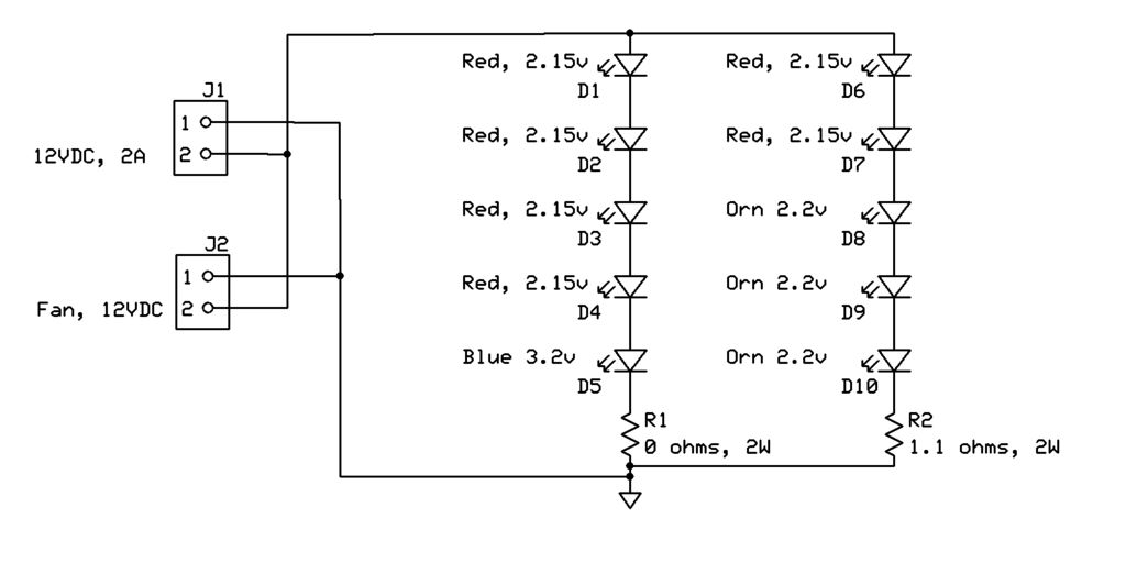
High-Brightness LED Grow-Light
This project page has evolved into a design discussion. Constructive suggestions and collaboration are still welcome. Please refer to the comments section.
The project focuses on the development of an electronic circuit design, which has transitioned from a simple project overview...
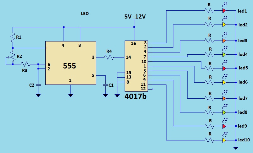
LED light chaser using 4017
This is a LED sequencer circuit where 10 LEDs light up and turn off sequentially, creating a chasing effect. This simple circuit is suitable for designing lighting decorations on Christmas trees. It can also be used for lighting animations by...
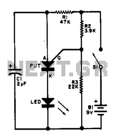
Led flasher IIV
This flasher circuit functions as a relaxation oscillator, with capacitor C1 discharging periodically through the LED when the Programmable Unijunction Transistor (PUT) is activated. The flashing rate is approximately 100 times per minute, based on the specified component values.
The flasher...
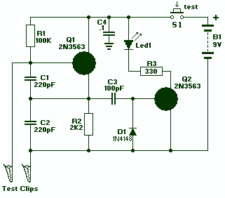
LED Crystal Tester
Transistor Q1, a 2N3563, and its associated components form an oscillator circuit that will oscillate if, and only if, a good crystal is connected to the test clips. The output from the oscillator is then rectified by the 1N4148 signal...
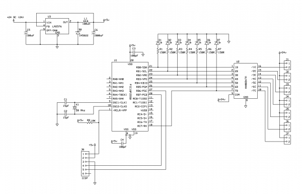
Christmas LED Light String Display
This project demonstrates the construction of a simple LED light string display utilizing seven 24V LED light strings. The project was designed for Christmas 2009 to adorn a balcony with lights. The light strings are widely available, particularly in Sweden,...
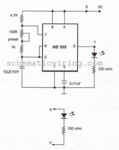
flash light electronic diagram
This circuit causes an LED to blink every half second. The duration of the blinking can be modified by changing the value of capacitor C1. Additionally, up to 18 more LEDs can be connected to this circuit, allowing for a...
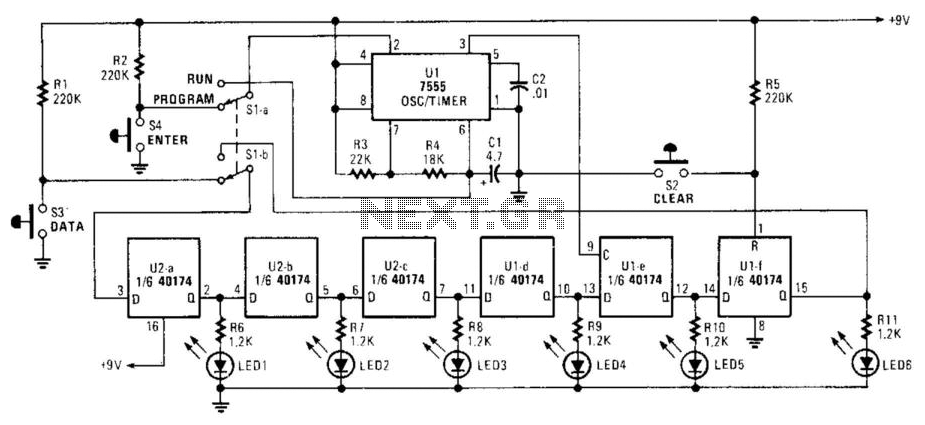
Light Chaser Ii
Up to six lights can be sequentially flashed using this circuit. LED1 through LED6 can be replaced by optocouplers (MOC3010, etc.) to control 120-Vac loads via triacs. Ul generates pulses that clock the shift register mode of the six D...
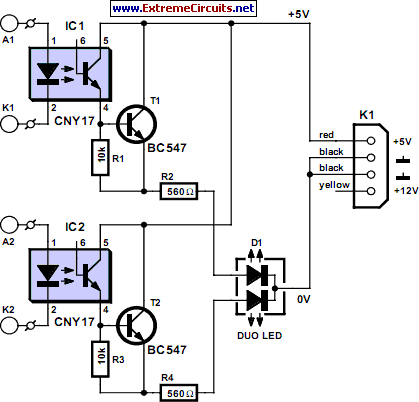
Multicolor HD LED
Most PC enclosures provide only a single LED to indicate hard disk access, with the LED being connected to the motherboard via a two-pin connector. However, this LED only works with IDE drives, and if a SCSI disk controller is...
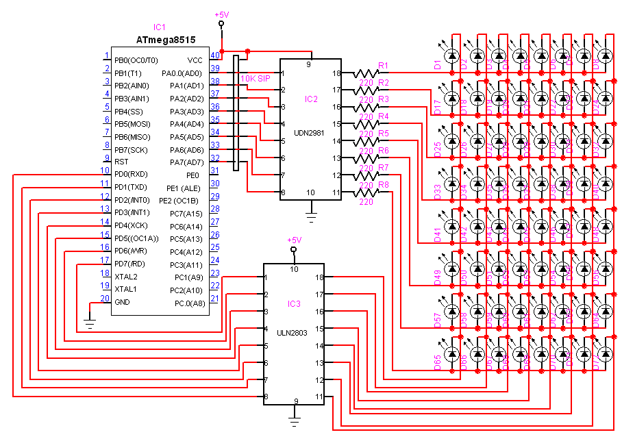
8G—8 Dotmatrix Scrolling LED display using atmega8515
Here is another project that creates a scrolling LED display. This display consists of 64 LEDs arranged in a matrix configuration. The anodes are driven through a driver circuit.
The scrolling LED display project utilizes a matrix of 64 LEDs, typically...