


Circuit diagram of brightness control relay
#brightness control
#relay
#light-sensitive resistor
#voltage divider
#resistor
#light sensor
#dimmer
#circuit control
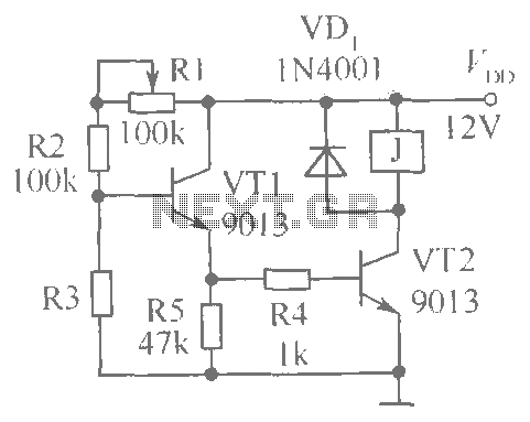
Description: This document presents a brightness control relay circuit. Resistors R1, R2, and R3 create a voltage divider circuit with a light-sensitive resistor. When the light level drops below a specific threshold, the base voltage of VT1 increases, causing VT1 and VT2 to conduct, which activates the relay. R1 is utilized to fine-tune the sensitivity of the circuit. The light-triggering level of the circuit is significantly affected by the supply voltage and ambient temperature.
The brightness control relay circuit is designed to automate the activation of devices based on ambient light conditions. The core of the circuit consists of a voltage divider formed by resistors R1, R2, and R3, in conjunction with a light-sensitive resistor (often a photoresistor). This configuration allows the circuit to monitor the intensity of light in the environment.
When the ambient light decreases to a predetermined level, the voltage at the base of transistor VT1 rises. This increase in voltage is crucial as it enables VT1 to turn on, which in turn activates VT2. The conduction of these transistors allows current to flow through the relay coil, energizing the relay and closing the contacts, which can be used to control various electrical devices such as lights or fans.
Resistor R1 plays an important role in setting the sensitivity of the circuit. By adjusting R1, the user can modify the threshold at which the circuit responds to changes in light levels. This feature is particularly useful in applications where varying light conditions are present, allowing for fine-tuning of the system's response.
It is essential to note that the performance of the light-triggering mechanism is influenced by both the supply voltage and the ambient temperature. Fluctuations in supply voltage can affect the operation of the transistors and the relay, while temperature changes can alter the resistance of the light-sensitive resistor, impacting the overall sensitivity and reliability of the circuit.
In summary, this brightness control relay circuit is a practical solution for automatic control of devices based on light intensity, with adjustable sensitivity and considerations for external factors such as supply voltage and temperature.Shown for the brightness control relay circuit. Resistors R1, R2 and R3 form a light-sensitive resistor voltage divider circuit, when the light is dark to a certain extent, VT1 base voltage rises to make VT1, VT2 conduction, the relay pull-J. R1 is used to adjust the motion sensitivity. The light trigger level circuit greatly influenced by the supply voltage and ambient temperature.
The brightness control relay circuit is designed to automate the activation of devices based on ambient light conditions. The core of the circuit consists of a voltage divider formed by resistors R1, R2, and R3, in conjunction with a light-sensitive resistor (often a photoresistor). This configuration allows the circuit to monitor the intensity of light in the environment.
When the ambient light decreases to a predetermined level, the voltage at the base of transistor VT1 rises. This increase in voltage is crucial as it enables VT1 to turn on, which in turn activates VT2. The conduction of these transistors allows current to flow through the relay coil, energizing the relay and closing the contacts, which can be used to control various electrical devices such as lights or fans.
Resistor R1 plays an important role in setting the sensitivity of the circuit. By adjusting R1, the user can modify the threshold at which the circuit responds to changes in light levels. This feature is particularly useful in applications where varying light conditions are present, allowing for fine-tuning of the system's response.
It is essential to note that the performance of the light-triggering mechanism is influenced by both the supply voltage and the ambient temperature. Fluctuations in supply voltage can affect the operation of the transistors and the relay, while temperature changes can alter the resistance of the light-sensitive resistor, impacting the overall sensitivity and reliability of the circuit.
In summary, this brightness control relay circuit is a practical solution for automatic control of devices based on light intensity, with adjustable sensitivity and considerations for external factors such as supply voltage and temperature.Shown for the brightness control relay circuit. Resistors R1, R2 and R3 form a light-sensitive resistor voltage divider circuit, when the light is dark to a certain extent, VT1 base voltage rises to make VT1, VT2 conduction, the relay pull-J. R1 is used to adjust the motion sensitivity. The light trigger level circuit greatly influenced by the supply voltage and ambient temperature.

light sensor
When connecting this element in a voltage divider configuration, a high and low signal can be generated based on the amount of light detected by the sensor. An NPN transistor configured as an inverter further filters this signal to produce...
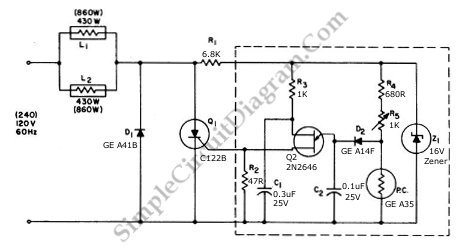
Low Cost Precision Light Control / Dimmer
This circuit utilizes a controlled half-plus-fixed half-wave phase control method to regulate an 860-watt lamp load, allowing operation from half to full power.
The circuit employs a phase control technique, which involves adjusting the phase angle of the AC voltage...
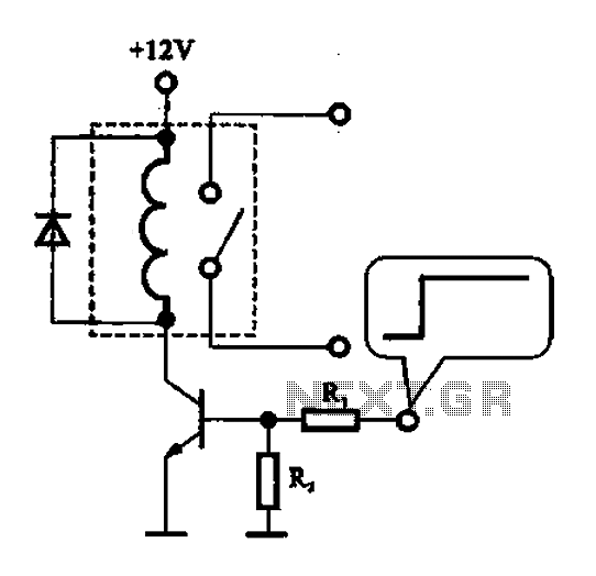
A relay control circuit
A relay control circuit is illustrated, which is commonly found in microwave switches. This circuit facilitates the operation of various components such as the power supply switch, electric fans, light bulbs, food turntables, and timers. The relay control signal circuit...
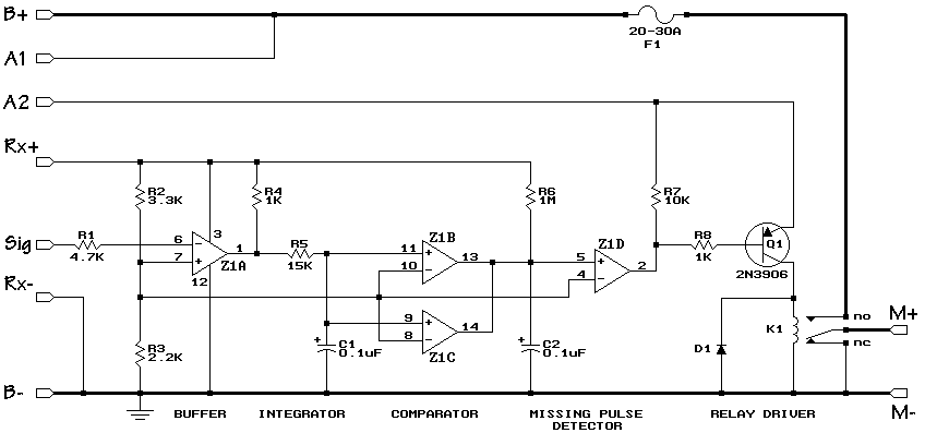
R/C On/Off Motor Controller with Brake
A relay-based on/off controller on the other hand can be very efficient. A typical relay has a contact resistance of 3 milliOhm. At 20A, this translates to a voltage drop of 0.06 volts, with a power loss of 1.2W. The...
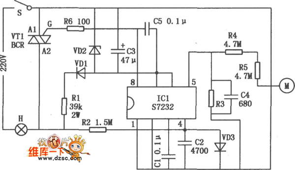
Touching dimmer circuit composed of S7232
A touch dimmer circuit is illustrated in the accompanying diagram. It utilizes a finger touch control piece to enable the turning on, off, or stepless adjustment of incandescent lighting. This circuit is applicable in dimming filament lamps and for the...
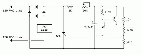
120 VAC Lamp Dimmer
The full-wave phase control circuit described was sourced from an RCA power circuits book published in 1969. In this configuration, the load is connected in series with the AC line, while four diodes are utilized to provide a full-wave rectified...
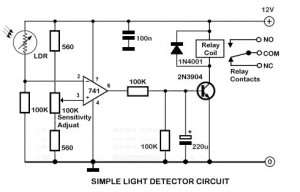
Light Sensor Circuit
An ambient light sensor circuit is a circuit that utilizes light intensity to perform various applications.
An ambient light sensor circuit typically consists of a light-dependent resistor (LDR) or phototransistor that detects the intensity of ambient light. The sensor converts the...
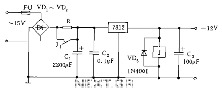
Relay type starting circuit diagram
The figure below illustrates the use of a relay in the starting circuit. The power input connects through a resistor R, which serves two purposes: first, it prevents a large current from the capacitor C1 from affecting the power supply...
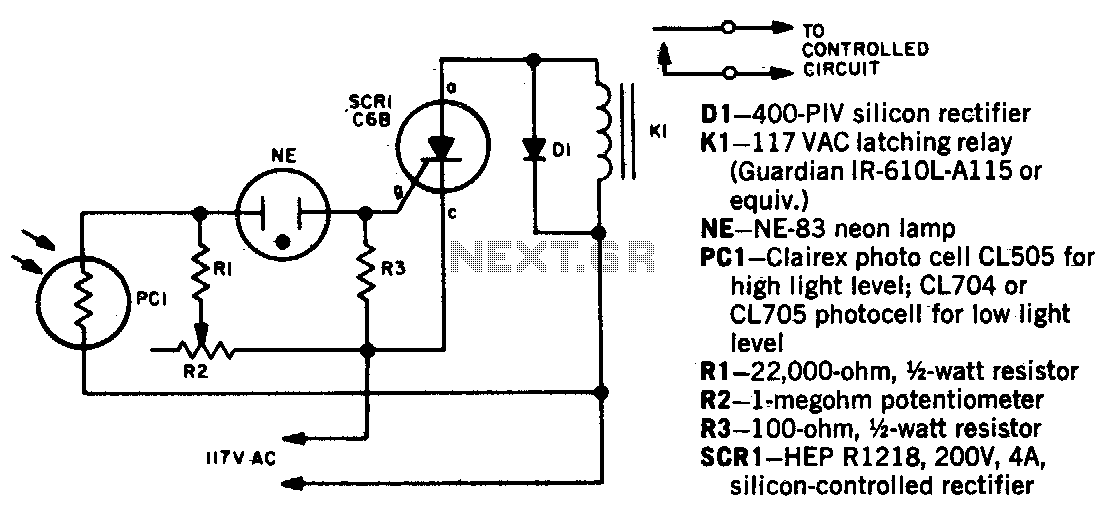
Light beam operated on-off relay
When a beam of light strikes the photocell, the voltage across the neon lamp NE-1 rises sharply. NE-1 turns on and triggers the SCR. K1 is an impulse relay whose contacts remain in position even after the coil current is...