


Code Reading Lamp
#dual colour lamp
#code reading
#transistors
#ICs
#low light
#electronics
#component identification
#workbench tool
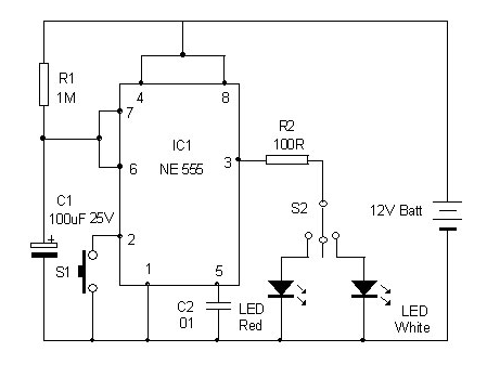
Description: This is a dual-color lamp designed to illuminate the codes printed on transistors and integrated circuits (ICs). The codes and numbers on the black bodies of these components can be challenging to read in low light conditions due to the faint colors or impressions used in the printing.
The dual-color lamp circuit can be designed using a simple LED configuration that allows for the selection of different colors based on user preference or specific requirements. The circuit typically consists of two LEDs, one emitting a warm white light and the other emitting a red light. This dual setup provides flexibility, as the warm white light can enhance visibility of the printed codes under normal conditions, while the red light can be used to minimize glare and preserve night vision when working in dark environments.
The circuit can be powered using a low-voltage power supply, such as a 5V USB source or a battery pack. A switch can be incorporated to toggle between the two LED colors. Resistors will be necessary to limit the current flowing through the LEDs to prevent damage. The selection of resistor values is crucial and can be calculated using Ohm's law, taking into account the forward voltage drop of the LEDs and the supply voltage.
A compact PCB layout can be designed to house the components, ensuring that the LEDs are positioned to provide optimal illumination across the work area. Additional features, such as an adjustable brightness control using a potentiometer, can enhance the usability of the lamp. This feature allows the user to set the appropriate brightness level based on the ambient light conditions.
Overall, the dual-color lamp serves as an essential tool for electronics enthusiasts and professionals, facilitating the reading of component codes in various lighting conditions.Here is a dual colour lamp to read the code printed on the Transistors and ICs. The code and number printed on the black coloured body of these components are difficult to read if the room light is low since the printing is in faint colour or as impressions..
The dual-color lamp circuit can be designed using a simple LED configuration that allows for the selection of different colors based on user preference or specific requirements. The circuit typically consists of two LEDs, one emitting a warm white light and the other emitting a red light. This dual setup provides flexibility, as the warm white light can enhance visibility of the printed codes under normal conditions, while the red light can be used to minimize glare and preserve night vision when working in dark environments.
The circuit can be powered using a low-voltage power supply, such as a 5V USB source or a battery pack. A switch can be incorporated to toggle between the two LED colors. Resistors will be necessary to limit the current flowing through the LEDs to prevent damage. The selection of resistor values is crucial and can be calculated using Ohm's law, taking into account the forward voltage drop of the LEDs and the supply voltage.
A compact PCB layout can be designed to house the components, ensuring that the LEDs are positioned to provide optimal illumination across the work area. Additional features, such as an adjustable brightness control using a potentiometer, can enhance the usability of the lamp. This feature allows the user to set the appropriate brightness level based on the ambient light conditions.
Overall, the dual-color lamp serves as an essential tool for electronics enthusiasts and professionals, facilitating the reading of component codes in various lighting conditions.Here is a dual colour lamp to read the code printed on the Transistors and ICs. The code and number printed on the black coloured body of these components are difficult to read if the room light is low since the printing is in faint colour or as impressions..
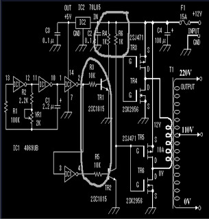
discussing output stage of square wave
The circuit includes 10K resistors at the bases of the transistors and 1K resistors at the collectors. It is essential to retain these components when relocating the transistors, as omitting the 10K resistors could result in transistor failure, and without...
Electronics Projects Circuits
Over 1400 top electronics projects and electronic circuits with photos, datasheets, and easy-to-read schematics, along with explanations of how they work and how to build them.
The collection comprises a vast array of electronics projects suitable for enthusiasts and professionals alike....
Oscillators and Triggers
Transistors are increasingly being utilized in various applications. Many circuits employing transistors have been developed based on previous designs that used vacuum tubes. The following chapters present unique applications that leverage the advantageous properties of transistors. The described circuits are...
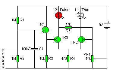
Lie detector
The circuit diagram of the Lie Detector is illustrated above. It consists of three transistors (TR1 to TR3), a capacitor (C1), two lights or LEDs (L1 & L2), five resistors (R1 to R5), and a variable resistor (VR1). This circuit...
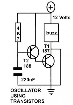
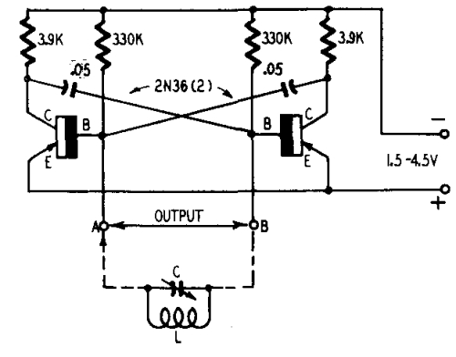
basic oscillator circuit using two
This schematic diagram represents a basic oscillator circuit utilizing two transistors. When the transistors and several passive components are connected as illustrated, the circuit begins to oscillate. The oscillation frequency can be modified by altering the values of either the...
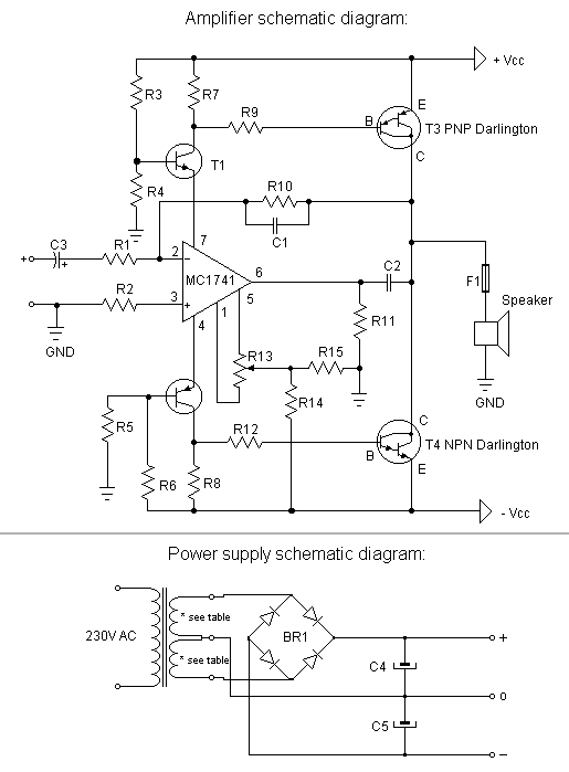
motorola hi fi power
The first step is to measure the amplification factor of the end transistors (T3 and T4), known as the hfe. If their difference exceeds 30%, the amplifier will produce unclear sound. In this case, MJ3001 and MJ2501 transistors were used,...
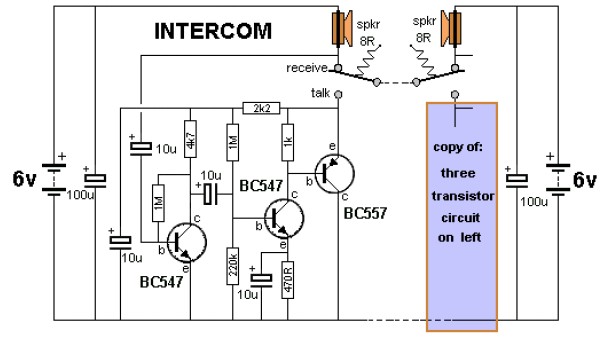
intercom circuit with transistors
The key to avoiding instability (motor-boating) in a high-gain circuit is to power the speaker using a separate power supply. This circuit design allows for the connection of one or two additional stations. It is recommended to construct the circuit...
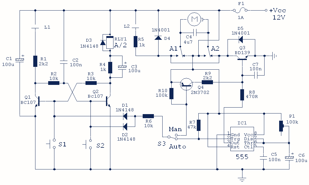
Curtain Control Circuit
This hybrid circuit uses a mixture of transistors, an IC and a relay and is used to automatically open or close a pair of curtains. Using switch S3 also allows manual control, allowing for curtains to be left only partially...
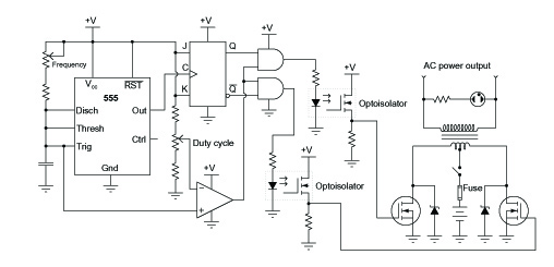
inverter circuit diagram
A common topology for DC-AC power converter circuits employs a pair of transistors to switch DC current through the center-tapped winding of a step-up transformer. Examine the check plot images from a PCB drafting program for a control board based...