


Commercial Stand-Light
#stand-light
#dynamo
#capacitor
#hub dynamo
#bottle dynamo
#power cutoff
#low speed operation
#commercial lighting
#energy efficiency
#circuit design
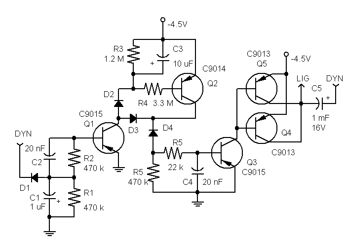
Description: This stand-light features a 1000 µF capacitor (C5) that connects the dynamo to the lights. The capacitor cuts off power to the lights at low speeds. While this effect may be negligible for a bottle dynamo, it could be problematic for a hub dynamo that operates at lower frequencies. The circuit functions as follows: an active dynamo charges capacitor C1 through diode D1, which turns on transistor Q1. When Q1 is activated, it charges capacitor C3, which then turns on transistor Q2. As long as Q1 remains on, current flows through Q2, diode D3, and Q1. When the dynamo ceases operation, C1 discharges rapidly, turning off Q1. With C3 still charged, Q2 stays on, but the current no longer flows through the now-off Q1; instead, it flows through resistor R5. This activates Q3, which in turn switches on transistors Q4 and Q5, connecting the battery to the lights. Once C3 discharges, Q2 turns off, followed by Q3, Q4, and Q5. Q4 and Q5 are arranged in parallel to prevent exceeding the maximum current (ICE) rating of 0.5 A for a single transistor, ensuring safe operation.
The circuit design incorporates a 1000 µF capacitor (C5) which plays a crucial role in managing power delivery to the lighting system. The capacitor acts as a buffer, allowing the lights to remain illuminated during brief interruptions in dynamo operation, particularly at low speeds. The choice of a larger capacitance value helps to smooth out fluctuations in voltage, particularly important for hub dynamos that may experience more significant drops in output at lower rotational speeds.
The charging sequence begins with the dynamo producing voltage, which is directed through diode D1 to charge capacitor C1. When C1 reaches a sufficient voltage, it activates transistor Q1. The activation of Q1 is pivotal as it initiates the charging of capacitor C3. The charging of C3 subsequently activates transistor Q2, which allows current to flow through the circuit, thereby powering the lights via the path that includes D3 and Q1.
In the event that the dynamo stops producing power, the rapid discharge of capacitor C1 results in the deactivation of Q1. However, the charge retained in C3 keeps Q2 active for a brief period. The current now redirects through resistor R5, allowing transistor Q3 to turn on. This action triggers transistors Q4 and Q5, which are configured in parallel to handle the load without risking damage to individual components. This parallel configuration is essential, as it distributes the current load, ensuring that neither transistor exceeds its rated maximum current of 0.5 A.
As capacitor C3 discharges, it eventually reaches a point where Q2 turns off, leading to the sequential deactivation of Q3, Q4, and Q5, effectively cutting power to the lights. This design ensures a reliable light source while maintaining the integrity and safety of the circuit components, making it suitable for various applications where dynamo-powered lighting is required.An interesting feature in this stand-light is the use of the 1000 uF capacitor C5 connecting the dynamo to the lights. The capacitor will be cutting off the power to the lights at low speeds. For a bottle dynamo, these would be such low speeds that the effect should be irrelevant. However, the effect may become unacceptable for a hub dynamo that operates at lower frequencies than bottle. Anyway, the circuit operates as follows. An operating dynamo charges the capacitor C1 through D1. This turns Q1 on. When Q1 is on, it charges the capacitor C3 which puts Q2 on. As long as Q1 is on, the current through Q2 flows through D3 and Q1. When the dynamo stops, C1 quickly discharges putting Q1 off. With C3 remaining charged, Q2 continues to be on, but now the current flows no more through Q1 that is off, but through R5. This puts Q3 on, which switches on Q4 and Q5 that connect the battery to the lights. After C3 discharges, Q2 goes off and so do Q3-Q5. Q4 and Q5 are connected in parallel because the use of one such transitor, with a max current ICE of 0.
5 A, would put that transistor too close to the boundary of its safe operation.
The circuit design incorporates a 1000 µF capacitor (C5) which plays a crucial role in managing power delivery to the lighting system. The capacitor acts as a buffer, allowing the lights to remain illuminated during brief interruptions in dynamo operation, particularly at low speeds. The choice of a larger capacitance value helps to smooth out fluctuations in voltage, particularly important for hub dynamos that may experience more significant drops in output at lower rotational speeds.
The charging sequence begins with the dynamo producing voltage, which is directed through diode D1 to charge capacitor C1. When C1 reaches a sufficient voltage, it activates transistor Q1. The activation of Q1 is pivotal as it initiates the charging of capacitor C3. The charging of C3 subsequently activates transistor Q2, which allows current to flow through the circuit, thereby powering the lights via the path that includes D3 and Q1.
In the event that the dynamo stops producing power, the rapid discharge of capacitor C1 results in the deactivation of Q1. However, the charge retained in C3 keeps Q2 active for a brief period. The current now redirects through resistor R5, allowing transistor Q3 to turn on. This action triggers transistors Q4 and Q5, which are configured in parallel to handle the load without risking damage to individual components. This parallel configuration is essential, as it distributes the current load, ensuring that neither transistor exceeds its rated maximum current of 0.5 A.
As capacitor C3 discharges, it eventually reaches a point where Q2 turns off, leading to the sequential deactivation of Q3, Q4, and Q5, effectively cutting power to the lights. This design ensures a reliable light source while maintaining the integrity and safety of the circuit components, making it suitable for various applications where dynamo-powered lighting is required.An interesting feature in this stand-light is the use of the 1000 uF capacitor C5 connecting the dynamo to the lights. The capacitor will be cutting off the power to the lights at low speeds. For a bottle dynamo, these would be such low speeds that the effect should be irrelevant. However, the effect may become unacceptable for a hub dynamo that operates at lower frequencies than bottle. Anyway, the circuit operates as follows. An operating dynamo charges the capacitor C1 through D1. This turns Q1 on. When Q1 is on, it charges the capacitor C3 which puts Q2 on. As long as Q1 is on, the current through Q2 flows through D3 and Q1. When the dynamo stops, C1 quickly discharges putting Q1 off. With C3 remaining charged, Q2 continues to be on, but now the current flows no more through Q1 that is off, but through R5. This puts Q3 on, which switches on Q4 and Q5 that connect the battery to the lights. After C3 discharges, Q2 goes off and so do Q3-Q5. Q4 and Q5 are connected in parallel because the use of one such transitor, with a max current ICE of 0.
5 A, would put that transistor too close to the boundary of its safe operation.
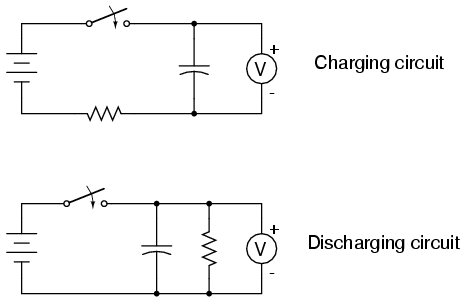
Capacitor charging and discharging
Large-value capacitors are necessary for this experiment to generate time constants slow enough to be monitored with a voltmeter and stopwatch. It is important to note that most large capacitors are of the "electrolytic" type, which are sensitive to polarity....
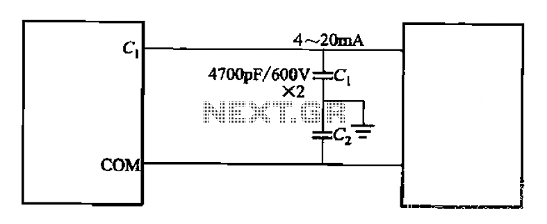
Control cables plus anti-interference capacitors
A capacitor filter is utilized in frequency control circuits and is a common method for implementing anti-jamming measures. It addresses frequency interference noise within the wiring of the 4-20mA control loop. The anti-interference is achieved through bypass capacitors C1 and...
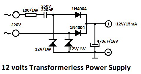
Capacitor Power Supply Circuit
One of the major problems that must be addressed in electronic circuit design is the generation of low voltage DC power supply from mains power to energize the circuit.
In electronic circuit design, the conversion of mains AC voltage to a...

Capacitor step-down DC power supply circuit
A capacitor step-down DC power supply circuit is presented. This circuit eliminates the need for power transformers, utilizing capacitive voltage drop rectification and regulation, which significantly reduces the overall size of the circuit. The circuit includes a capacitor step-down component,...
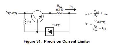
Capacitor Charging Circuit
This Korean SuperCap OEM supports usage in series configurations. Consider whether the implementation will be manual or automatic, such as with a smart battery charger or a power fail backup circuit. It is essential to balance the voltage and provide...

adj pwr
The design incorporates a universal capacitor mounting and spacing feature, enabling compatibility with various capacitor types. It includes a mounting pattern suitable for TO-200 or TO-218/247 packages, specifically for the pass transistor and the transistor utilized in the current limit...
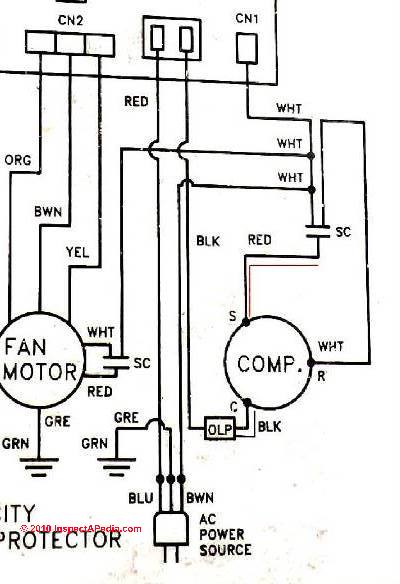
Starting Capacitors
Instructions for electric motor start-run capacitors include the use of starting capacitors for air conditioner compressor motors and other electric motors like pumps. This involves diagnostic checks for start or run capacitors, including how to use a volt-ohm meter (VOM)...
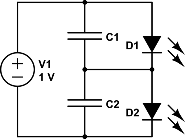
Charging a low-voltage high-C capacitor. Efficiently
The first option is a Zener diode. There are several 2.2V Zener diodes available that could adequately protect the capacitor. However, a significant drawback is that half the energy may be wasted across the diode short. The question arises whether...
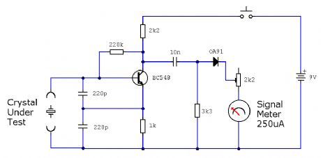
ELF MONITOR
The capacitor instrument is not intended for measuring the capacitance of capacitors; rather, it is designed to identify whether a capacitor is functional or defective, as well as to detect short circuits or open circuits. This functionality provides reliable quality...