


Constant-brightness-control
#constant brightness
#photodiode
#phase angle control
#lamp control
#automatic control
#power line voltage
#brightness regulation
#lighting
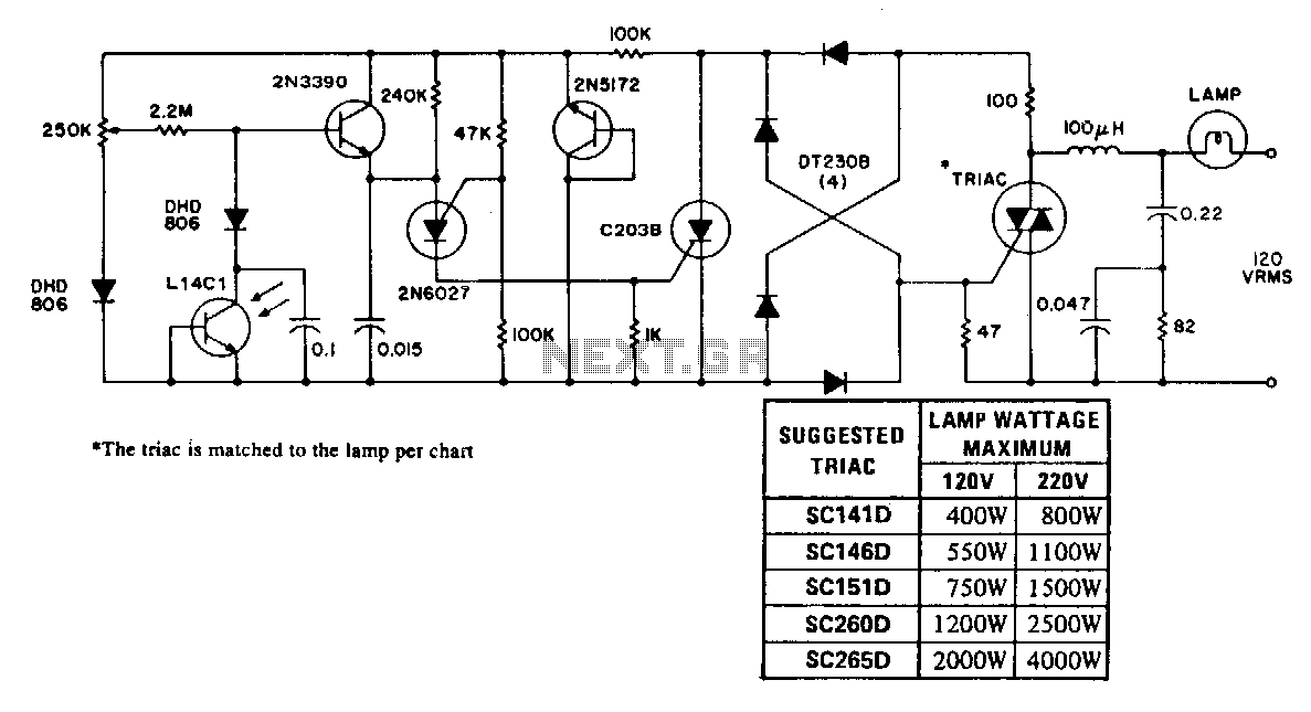
Description: An automatic control maintains a lamp at a constant brightness over a wide range of supply voltages. This circuit utilizes the consistency of photodiode response to control the phase angle of power line voltage applied to the lamp and can vary the power between that available and 30% of available. This provides a candlepower range from 100% to less than 10% of nominal lamp output. The 100 μH choke, resistor, and capacitors form an RFI filter network that is used to eliminate conducted RFI.
The described circuit employs a feedback mechanism that leverages a photodiode to detect the brightness of the lamp. The photodiode's output is proportional to the light intensity, which is then processed to adjust the phase angle of the AC voltage supplied to the lamp. By controlling the phase angle, the effective power delivered to the lamp can be modulated, allowing for a smooth dimming effect. The system is designed to operate effectively across a wide range of input voltages, ensuring consistent performance irrespective of fluctuations in the power supply.
The circuit's ability to reduce power down to 30% of the available supply voltage ensures that users can achieve a dimming capability that ranges from full brightness (100% output) to a very low output (less than 10% of nominal). This feature is particularly useful in applications where ambient light levels need to be adjusted for comfort or energy efficiency.
To ensure the reliability of the circuit and compliance with electromagnetic interference standards, a filter network composed of a 100 μH choke, resistors, and capacitors is integrated into the design. This network functions as a low-pass filter, effectively attenuating any conducted radio frequency interference (RFI) that may be present in the power line. The choke provides inductive reactance that opposes rapid changes in current, while the combination of resistors and capacitors works to smooth out voltage fluctuations, thereby maintaining stable operation of the lamp control circuit.
Overall, this automatic control circuit represents a sophisticated solution for managing lamp brightness in varying electrical environments, combining effective dimming capabilities with robust noise filtering to ensure optimal performance.An automatic control maintains a lamp at a constant brightness over a wide range of supply voltages. This circuit utilizes the consistency of photodiode response to control the phase angle of power line voltage applied to the lamp and can vary the power between that available and "" 30% of available. This provides a candlepower range from 100% to less than 10% of nominal lamp output. The 100-J.tH choke, resistor, and capacitors form an ric filter network that is used to eliminate conducted RFI.
The described circuit employs a feedback mechanism that leverages a photodiode to detect the brightness of the lamp. The photodiode's output is proportional to the light intensity, which is then processed to adjust the phase angle of the AC voltage supplied to the lamp. By controlling the phase angle, the effective power delivered to the lamp can be modulated, allowing for a smooth dimming effect. The system is designed to operate effectively across a wide range of input voltages, ensuring consistent performance irrespective of fluctuations in the power supply.
The circuit's ability to reduce power down to 30% of the available supply voltage ensures that users can achieve a dimming capability that ranges from full brightness (100% output) to a very low output (less than 10% of nominal). This feature is particularly useful in applications where ambient light levels need to be adjusted for comfort or energy efficiency.
To ensure the reliability of the circuit and compliance with electromagnetic interference standards, a filter network composed of a 100 μH choke, resistors, and capacitors is integrated into the design. This network functions as a low-pass filter, effectively attenuating any conducted radio frequency interference (RFI) that may be present in the power line. The choke provides inductive reactance that opposes rapid changes in current, while the combination of resistors and capacitors works to smooth out voltage fluctuations, thereby maintaining stable operation of the lamp control circuit.
Overall, this automatic control circuit represents a sophisticated solution for managing lamp brightness in varying electrical environments, combining effective dimming capabilities with robust noise filtering to ensure optimal performance.An automatic control maintains a lamp at a constant brightness over a wide range of supply voltages. This circuit utilizes the consistency of photodiode response to control the phase angle of power line voltage applied to the lamp and can vary the power between that available and "" 30% of available. This provides a candlepower range from 100% to less than 10% of nominal lamp output. The 100-J.tH choke, resistor, and capacitors form an ric filter network that is used to eliminate conducted RFI.
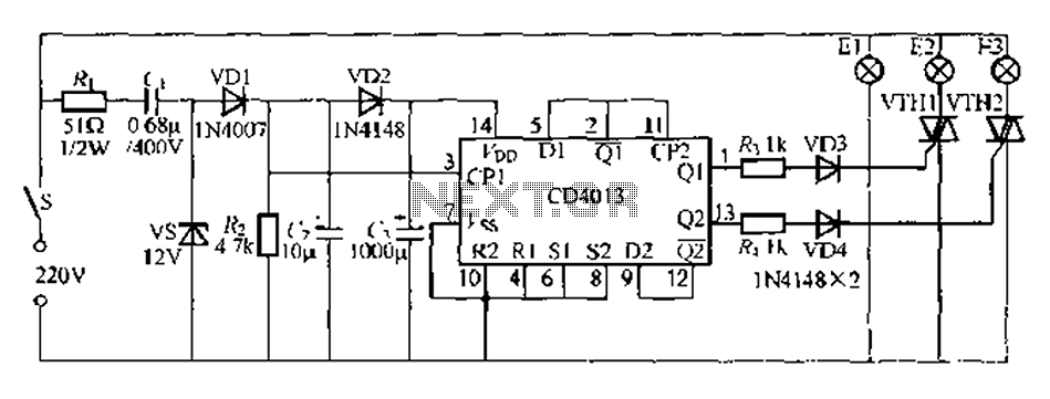
Single multi-lamp switch control circuit 2
Figure 296 illustrates a control circuit that utilizes a switch (S) to manage three lamps (E1, E2, and E3) in a lighting system, suitable for controlling a chandelier in a living room. When the switch is off, all lights are...
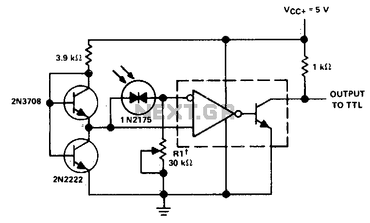
Precision photodiode comparator
Rl sets the comparison level. At comparison, the photodiode has less than 5 mV across it, decreasing dark current by an order of magnitude. More: IC = LM 111/211/311.
In this circuit description, the resistor Rl plays a crucial role in...
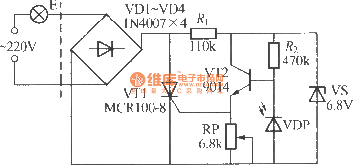
Simple light-operated street lamp circuit diagram(3)
The VDP is a photodiode that exhibits low resistance during the day, approximately 1 kΩ. As a result, transistor VT2 remains off, which keeps thyristor VT1 in the off-state due to the absence of trigger current at the gate, preventing...
Photodiode current-to-voltage converter
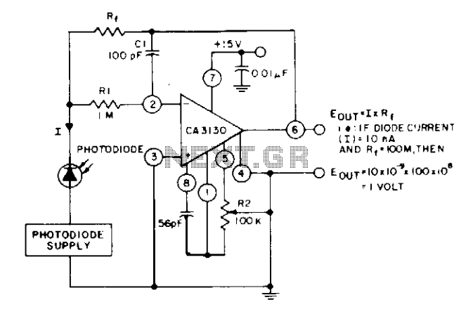
The circuit utilizes three CA3130 BiMOS operational amplifiers in an application that is sensitive to sub-picoampere input currents. It provides a ground-referenced output voltage that is proportional to the input current flowing through the photodiode.
The circuit design employs three CA3130...
Photodiode current-to-voltage converter
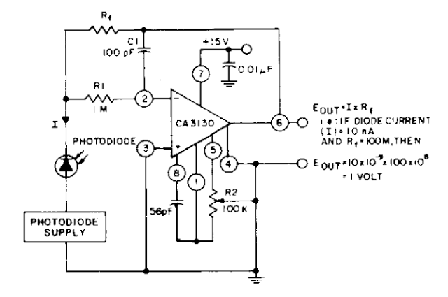
The photodiode current-to-voltage converter circuit employs three CA3130 BiMOS operational amplifiers, designed for applications that require sensitivity to sub-picoampere input currents. This circuit generates a ground-referenced output voltage that is directly proportional to the input current flowing through the photodiode.
The...
Precision photodiode level detector
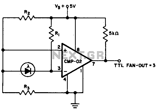
The output state changes at a photodiode current of 0 µA. For R1 = 2 MΩ, R2 = R3 = 5 MΩ.
The described circuit likely involves a photodiode used in conjunction with resistors R1, R2, and R3 to create a...
Photodiode-source-follower
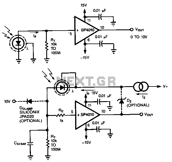
A common method of transforming the output current of a photodiode into a voltage signal involves paralleling the photodiode with a high-value load resistor, which results in a nonlinear response. Additionally, the combination of the load's transresistance, Rr, and the...
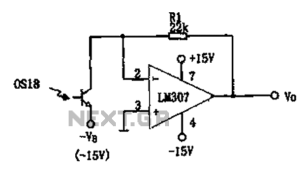
Photoreceiving circuit diagram LM307 amplifier configuration
The circuit described is a photoelectric receiver amplifier designed to amplify the electrical signals generated by photodiodes or phototransistors in optoelectronic devices. When the intensity of incident light varies, the photosensitive device generates a corresponding voltage or current. The photoreceptor...
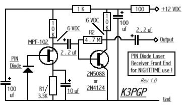
Modulated Light DX
Which type of modulated light receiver should be used? A photodiode directly connected to a high-gain, high-impedance amplifier; a photodiode connected to a current amplifier; a back-biased photodiode; FET input or bipolar IC or discrete components? How can noise be...