


Constantly changing light and sound analog controller circuit 05
#analog controller
#light control
#sound control
#LED
#circuit 05
#changing light
#changing sound
#analog circuit
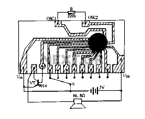
Description: Constantly changing light and sound analog controller circuit 05
The circuit described is an analog controller designed to modulate light and sound in a dynamic manner. This type of circuit typically employs a combination of resistors, capacitors, and operational amplifiers to create varying signals that influence the intensity of light sources, such as LEDs, and the output of sound devices, such as speakers or buzzers.
In this specific design, the core functionality relies on the use of a variable resistor or potentiometer that adjusts the level of input signals. These signals are then processed through an operational amplifier configured in a feedback loop to ensure stability and responsiveness. The output can drive a light-emitting diode (LED) or a small speaker, providing a visual or auditory response that continuously changes based on the input parameters.
To implement this circuit, a power supply is required, typically in the range of 5V to 12V, depending on the components used. The circuit may also include a microcontroller to further enhance the control capabilities, allowing for complex modulation patterns and integration with other electronic systems.
The analog controller circuit can be enhanced by incorporating additional elements such as light sensors or microphones, which can adjust the output based on ambient conditions, creating an interactive experience. By fine-tuning the values of the passive components, the response time and sensitivity of the circuit can be optimized for specific applications, making it suitable for artistic installations, educational tools, or entertainment systems.
Overall, this circuit offers a versatile platform for exploring the interplay between sound and light, providing endless opportunities for creative expression and technological experimentation.Constantly changing light and sound analog controller circuit 05
The circuit described is an analog controller designed to modulate light and sound in a dynamic manner. This type of circuit typically employs a combination of resistors, capacitors, and operational amplifiers to create varying signals that influence the intensity of light sources, such as LEDs, and the output of sound devices, such as speakers or buzzers.
In this specific design, the core functionality relies on the use of a variable resistor or potentiometer that adjusts the level of input signals. These signals are then processed through an operational amplifier configured in a feedback loop to ensure stability and responsiveness. The output can drive a light-emitting diode (LED) or a small speaker, providing a visual or auditory response that continuously changes based on the input parameters.
To implement this circuit, a power supply is required, typically in the range of 5V to 12V, depending on the components used. The circuit may also include a microcontroller to further enhance the control capabilities, allowing for complex modulation patterns and integration with other electronic systems.
The analog controller circuit can be enhanced by incorporating additional elements such as light sensors or microphones, which can adjust the output based on ambient conditions, creating an interactive experience. By fine-tuning the values of the passive components, the response time and sensitivity of the circuit can be optimized for specific applications, making it suitable for artistic installations, educational tools, or entertainment systems.
Overall, this circuit offers a versatile platform for exploring the interplay between sound and light, providing endless opportunities for creative expression and technological experimentation.Constantly changing light and sound analog controller circuit 05
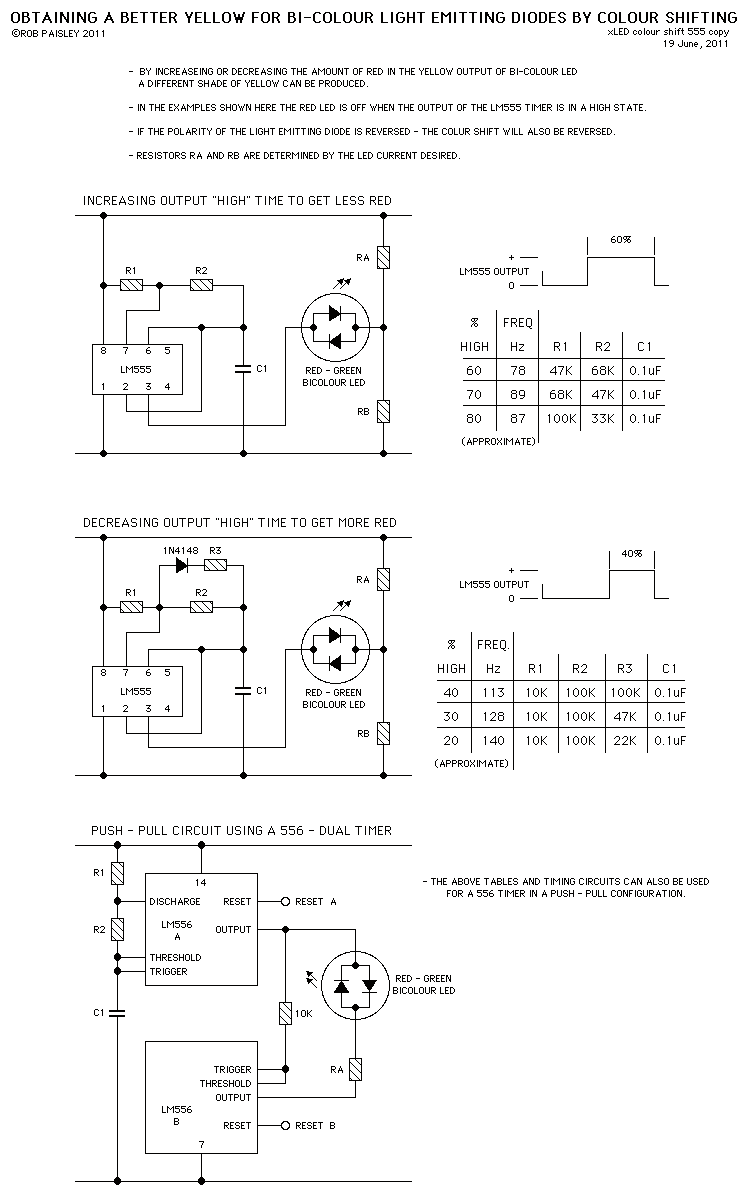
Colour Shifting LED`s
These circuits provide a means of altering the YELLOW output of RED / GREEN type two colour light emitting diodes. These circuits use the LM555 timer chip.
The circuit described utilizes the LM555 timer integrated circuit (IC) to modulate the output...
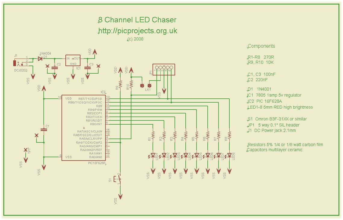
led chaser pwm
This compact circuit operates 8 LEDs directly driven from a PIC microcontroller, accompanied by a single mode control switch. The firmware controls the LEDs using a 5-bit PWM signal, enabling four levels of intensity for each LED channel: off, dim,...
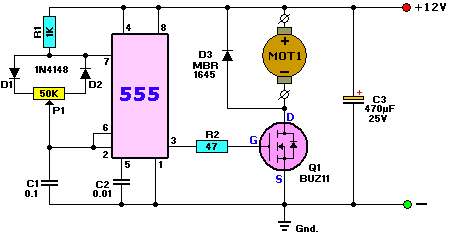
LED Dimmer Lighting
A dimmer for individual LED bulbs. LEDs (light emitting diodes) are very sensitive components; exceeding their rated current or voltage can drastically reduce their lifespan from over 50,000 hours to mere microseconds. LEDs are current-driven, meaning that the intensity of...
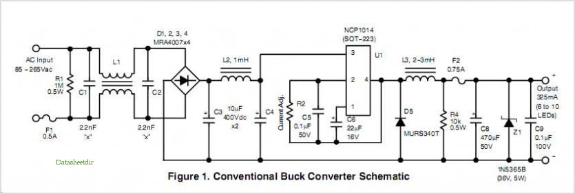
700 Ma Led Power Supply circuit using Monolithic Controller
Quasi square wave resonant converters, also referred to as quasi resonant (QR) converters, facilitate the design of flyback Switch Mode Power Supplies (SMPS) with diminished Electro Magnetic Interference (EMI) and enhanced efficiency. Due to their low noise generation, QR SMPS...
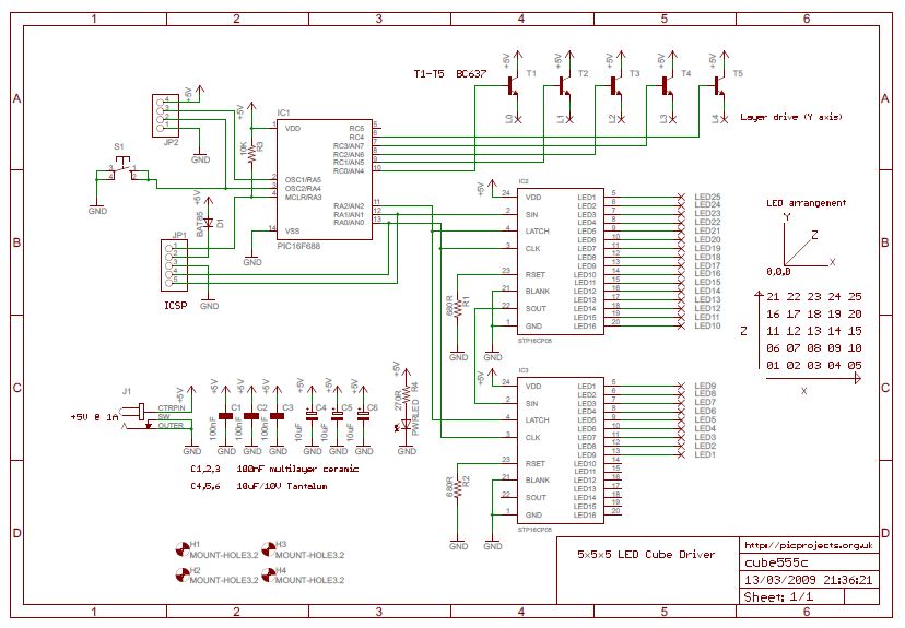
LED
This series of light switches operates differently from traditional voltage-based systems. These light switches can function directly on the AC power network. The primary components utilized in this circuit are a TRIAC and a Light Dependent Resistor (LDR). The circuit...
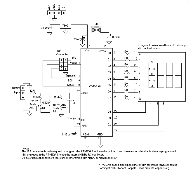
LED Digital Panel Meter
To explain in a little more detail, using the ATMEGA8's internal 2.5 volt band gap reference means that by using a resistive divider ahead of the A-to-D converter, the input could be scaled such that any voltage range from 0...
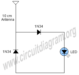
cell phone signal activated led
A simple and interesting project schematic for a cell phone signal-activated LED circuit. The circuit will illuminate an LED when a call is made from a cell phone.
This cell phone signal-activated LED circuit utilizes a basic principle of detecting the...
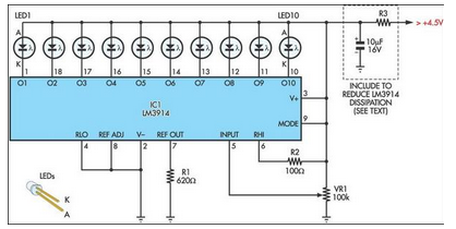
Novel White LED Torch
This design is directly reproduced from the manufacturer's datasheets; however, its application in this context is quite innovative. Originally intended for high-performance applications...
This circuit design utilizes components specified in the manufacturer's datasheets, ensuring adherence to the recommended specifications for optimal...
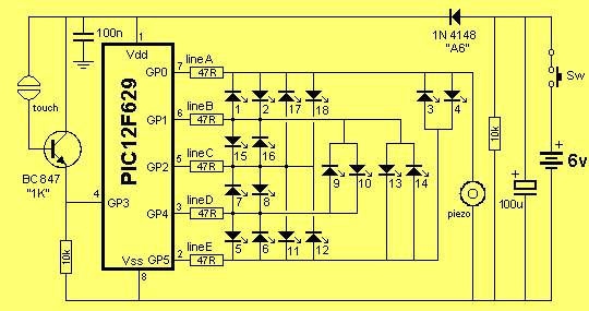
STRESS METER
It consisted of 16 LEDs in a circle with two touch pads. By placing your fingers on the touch pads, the circuit started and ran the LEDs in a "chaser" pattern around the display, with a beep each time a...