


DCDC single cell flashlight drive circuit diagram
#DC-DC
#flashlight
#battery
#driver circuit
#1.5V
#LED
#power conversion
#single cell
#simple circuit
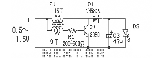
Description: This is a simple and easy-to-build DC-DC driver circuit designed for a single flashlight battery, operating at a parametric voltage of 1.5V. The input current is 90mA, while the light-emitting diode (LED) current is 26mA or higher. The circuit can utilize a magnet detached from waste energy-saving lamps, and diodes such as 1N5819 or 1N4148 can be used as alternatives. If a 47μF tantalum capacitor is unavailable, it can be replaced with an electrolytic capacitor in the range of 25-47μF, which may result in slightly lower efficiency. The circuit is intended for modified single-cell flashlights.
The DC-DC driver circuit for a single flashlight battery is designed to efficiently convert the low voltage of the battery into a higher voltage suitable for LED operation. The circuit typically employs a boost converter topology, where an inductor, a switch (usually a transistor), a diode, and a capacitor are used to step up the voltage. In this case, the circuit operates with a 1.5V input, which is standard for alkaline or NiMH batteries.
The input current of 90mA indicates that the circuit is designed to draw a relatively low amount of power from the battery, ensuring longer operational time. The output current for the LED is specified to be 26mA or more, which is sufficient for driving standard LEDs, providing adequate brightness while maintaining efficiency.
The inclusion of a diode such as the 1N5819 or 1N4148 is crucial for preventing backflow of current, ensuring that the energy stored in the inductor is directed towards the load (in this case, the LED). These diodes are selected for their low forward voltage drop, which contributes to the overall efficiency of the circuit.
Capacitors play a vital role in smoothing the output voltage and stabilizing the circuit. While a 47μF tantalum capacitor is ideal for this application, the use of electrolytic capacitors in the range of 25-47μF is a practical alternative. Although this substitution may lead to a minor decrease in efficiency, it allows for flexibility in component selection based on availability.
Overall, this circuit is an excellent solution for powering LED applications in single-cell flashlights, providing an efficient means of utilizing low-voltage battery power while ensuring adequate brightness for the LED. The design is straightforward, making it accessible for hobbyists and engineers looking to create energy-efficient lighting solutions.Simple and easy to do single flashlight battery DC-DC driver circuit and leave the battery production. Figure Parametric voltage 1.5V, the input current is 90mA light emitting tube current 26mA or more. Magnet detached from the waste energy-saving lamps, diode 1N5819 1N4148 find available alternative. 47uF tantalum capacitors can not find, can also be used instead of electrolytic capacitors 25-47uF, only slightly lower efficiency, even though there are so luminous tube current 20mA. Modified single cell flashlight pays.
The DC-DC driver circuit for a single flashlight battery is designed to efficiently convert the low voltage of the battery into a higher voltage suitable for LED operation. The circuit typically employs a boost converter topology, where an inductor, a switch (usually a transistor), a diode, and a capacitor are used to step up the voltage. In this case, the circuit operates with a 1.5V input, which is standard for alkaline or NiMH batteries.
The input current of 90mA indicates that the circuit is designed to draw a relatively low amount of power from the battery, ensuring longer operational time. The output current for the LED is specified to be 26mA or more, which is sufficient for driving standard LEDs, providing adequate brightness while maintaining efficiency.
The inclusion of a diode such as the 1N5819 or 1N4148 is crucial for preventing backflow of current, ensuring that the energy stored in the inductor is directed towards the load (in this case, the LED). These diodes are selected for their low forward voltage drop, which contributes to the overall efficiency of the circuit.
Capacitors play a vital role in smoothing the output voltage and stabilizing the circuit. While a 47μF tantalum capacitor is ideal for this application, the use of electrolytic capacitors in the range of 25-47μF is a practical alternative. Although this substitution may lead to a minor decrease in efficiency, it allows for flexibility in component selection based on availability.
Overall, this circuit is an excellent solution for powering LED applications in single-cell flashlights, providing an efficient means of utilizing low-voltage battery power while ensuring adequate brightness for the LED. The design is straightforward, making it accessible for hobbyists and engineers looking to create energy-efficient lighting solutions.Simple and easy to do single flashlight battery DC-DC driver circuit and leave the battery production. Figure Parametric voltage 1.5V, the input current is 90mA light emitting tube current 26mA or more. Magnet detached from the waste energy-saving lamps, diode 1N5819 1N4148 find available alternative. 47uF tantalum capacitors can not find, can also be used instead of electrolytic capacitors 25-47uF, only slightly lower efficiency, even though there are so luminous tube current 20mA. Modified single cell flashlight pays.
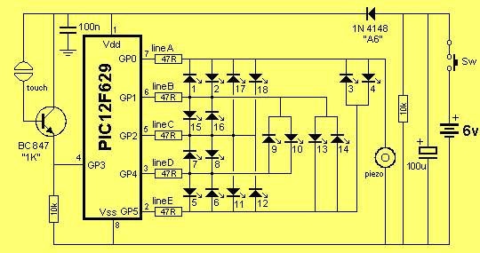
STRESS METER
It consisted of 16 LEDs in a circle with two touch pads. By placing your fingers on the touch pads, the circuit started and ran the LEDs in a "chaser" pattern around the display, with a beep each time a...
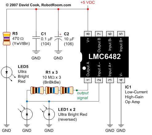
Using LEDs as colour sensors
This circuit converts the analog signal from the reversed LED, which is in sensing mode, and amplified by the operational amplifier, into a digital (on/off) signal. The original complex design has been simplified. An alternative approach is discussed in a...
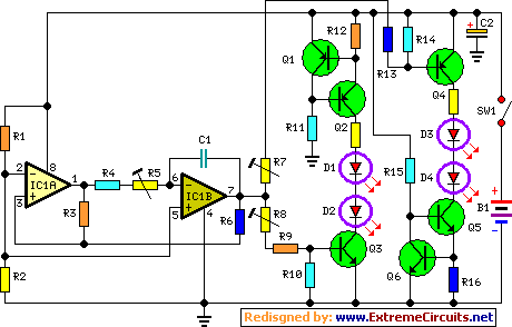
Fading LedsCircuit
This circuit operates two LED strips in a pulsing mode, where one LED strip transitions from an off state to gradually lighting up and then dimming, while the other LED strip performs the opposite action. Each strip can consist of...
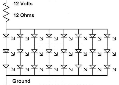
ve170 monitor repair with led
The issue with this monitor is that the power supply for the vacuum tube backlighting fails. The initial step involves completely disassembling the monitor into smaller components, followed by the careful removal of the gold-colored trays that hold the vacuum...
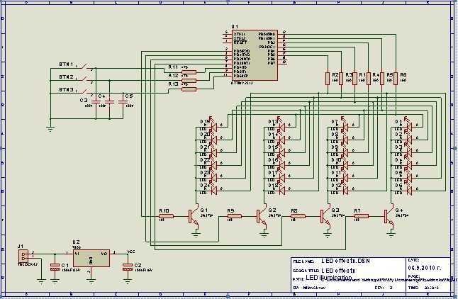
LED effects with ATTYNI2313
This project I made for my little daughter. It is 24 channel light illumination. The schematic is very simple 24 LEDs, 1 MCU and some additional components. The main principle is dynamic indication, which is usually implemented for control of...
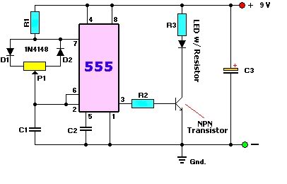
LED dimmer circuit
A user is new to the forum and has limited experience in DIY electronics. The current project involves creating a battery-powered LED dimmer circuit.
The objective of the project is to design a battery-operated LED dimmer circuit that allows for adjustable...
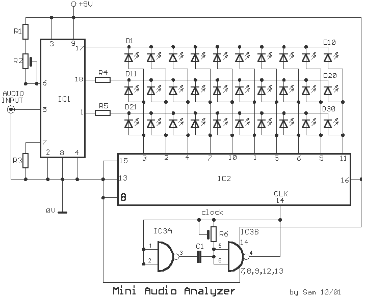
30 LED audio frequency analyzer
This analyst is a sensitive instrument in the frequency changes and width of an acoustic signal. Thus, the brightness of the LED that turns on each moment is proportional to the signal width, while the color is proportional to the...
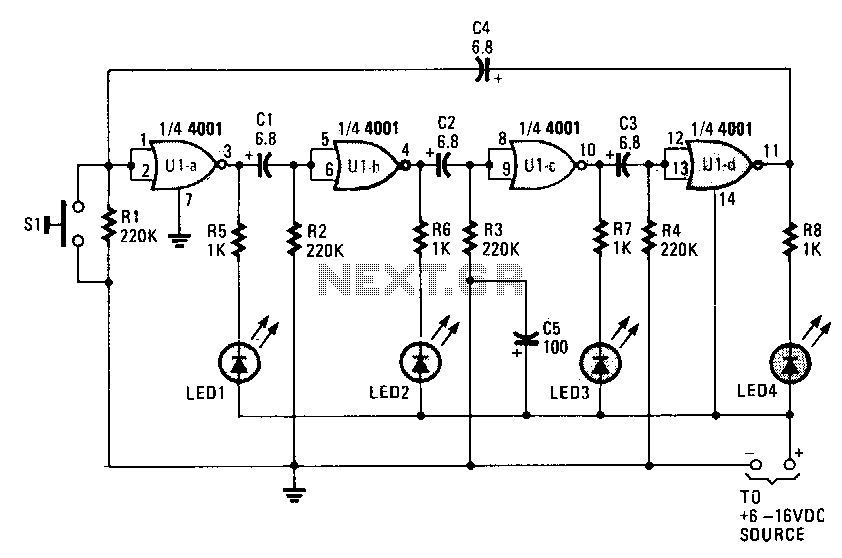
Ring-around-led-flasher
When power is initially applied, two of the LEDs illuminate while the other two remain off until the timing cycle reverses. The LEDs flash in pairs; however, by pressing and holding switch S1 until only one LED is lit, and...
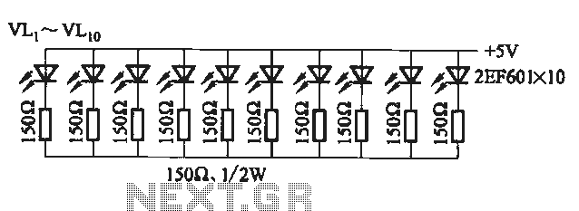
Flicker frequency of multiple sets of different light-emitting diode lights chain circuit
The circuit utilizes a 555 timer configured as a multivibrator, where the oscillation frequency is determined by resistors R1, R2, and capacitor C1. The frequency formula is given by fo = 1.443 / ((R1 + R2) * C1). The output...