


diac controlled led flasher 3
#diac
#LED
#flasher
#AC
#Mains
#indicator
#pulse generator
#high voltage
#simple circuit
#mock flasher
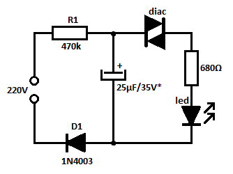
Description: This is likely the simplest concept for generating a flashing light from an LED using alternating current (AC). The circuit provides a straightforward method for flashing one or more LEDs using high-voltage direct current (DC) sourced from mains electricity. It can serve as a mains indicator or a mock flasher. The circuit incorporates a diac for the alternating switching of the LED. Diacs are typically utilized in pulse generator circuits to trigger silicon-controlled rectifiers (SCRs) and triacs. When a low voltage is applied to a diac, it behaves like an open circuit, allowing only a minimal current to flow. However, once the voltage exceeds the breakdown threshold of the diac, it permits a significant current to pass. Generally, a threshold of approximately 35 volts DC is necessary to activate the diac. Unlike SCRs, diacs conduct in both directions. In this circuit, a commonly available DB3 diac is employed. Diode D1 rectifies the AC input and produces a high-voltage DC output. Resistor R1 regulates the DC voltage to safely operate the diac and the LED. Under normal conditions, the LED remains off. Once the capacitor is fully charged, the diac reaches its threshold voltage and activates, allowing current to flow to the LED, illuminating it. Resistor R2 limits the LED current to a safe value of 30 mA. When the diac conducts, capacitor C1 discharges, which subsequently lowers the breakdown voltage of the diac, causing the LED to turn off. This charging and discharging cycle of C1 results in the LED flashing. The capacitance value of C1 determines the flash rate; larger capacitance values yield a slower flash rate, while smaller values produce a faster rate. If the threshold voltage of the diac is not achieved with the current value of R1, it can be reduced to 10 kΩ, but its power rating should be increased to 5 watts. Caution is advised, as the circuit is directly connected to high-voltage AC with no galvanic isolation. Extreme care must be taken when handling the circuit, and it should be encased in a shockproof enclosure. Avoid touching any components while the circuit is connected to mains power.
The circuit design described utilizes a straightforward approach to create a flashing LED effect. The key component, the diac, operates as a switch that allows current to flow once the voltage exceeds its threshold, thus controlling the LED's illumination. The inclusion of diode D1 ensures that the alternating current is converted into a usable direct current, which is essential for the operation of the diac and LED. Resistor R1 is critical for limiting the current flowing into the diac, preventing damage and ensuring reliable operation. Resistor R2 serves to further protect the LED by restricting the current to a safe level, preventing potential burnout.
The capacitor C1 plays a vital role in determining the flashing frequency of the LED. By adjusting its capacitance, one can control how quickly the LED turns on and off. This feature allows for customization of the flashing effect, making it suitable for various applications, such as decorative lighting or indicators. The circuit's simplicity makes it an excellent choice for educational purposes, demonstrating fundamental concepts in electronics such as rectification, capacitive charging, and the operation of diacs.
Safety precautions are paramount given the high-voltage nature of the circuit. Proper insulation and housing are necessary to prevent accidental contact with live components. Additionally, the circuit should be tested and operated in a controlled environment to mitigate risks associated with high voltage. Overall, this circuit exemplifies a practical application of basic electronic components to achieve a visually engaging outcome while highlighting essential safety considerations.This is probably the simplest idea to generate flashing light from an LED using AC. The circuit is relatively the simple way of flashing one or more LEDs from a high voltage DC obtained from Mains. This can be used as a Mains indicator or Mock flasher. The circuit uses a diac for the alternate switching of LED. The diac is usually used in pulse ge nerator circuits to trigger SCR and Triac. If a low voltage passes through a diac, it simply behaves like an open circuit and only very low current passes through it. But if the voltage increases to the breakdown threshold of the diac, it will pass heavy current. Usually 35 volt DC is required to attain the threshold level of diac. Unlike SCR, diac conduct in both the directions. In the circuit, a commonly available DB3 diac is used. Diode D1 rectifies AC and generates a high volt DC. Resistor R1 safely controls the DC to operate diac and LED. Normally LED will be OFF. When the capacitor charges fully, diac gets the threshold voltage and fires. This provides current to LED and it lights. Resistor R2 makes the LED current to a safer value of 30 mA. When the diac conducts, C1 discharges and again the breakdown voltage of diac decreases and LED turns off.
Thus the charging/discharging cycles of C1 makes the LED flashing. The value of C1 determines the flash rate. Higher values give slow flash rate and vice versa. If the threshold level of diac is not obtained using the given value of R1, reduce it to 10K, but its wattage should be increased to 5 watts. Caution The circuit is directly connected to high volt AC and there is no galvanic isolation. Take utmost care while handling the circuit. Enclose it in a shock proof case. Do not touch any points when it is connected to Mains.
The circuit design described utilizes a straightforward approach to create a flashing LED effect. The key component, the diac, operates as a switch that allows current to flow once the voltage exceeds its threshold, thus controlling the LED's illumination. The inclusion of diode D1 ensures that the alternating current is converted into a usable direct current, which is essential for the operation of the diac and LED. Resistor R1 is critical for limiting the current flowing into the diac, preventing damage and ensuring reliable operation. Resistor R2 serves to further protect the LED by restricting the current to a safe level, preventing potential burnout.
The capacitor C1 plays a vital role in determining the flashing frequency of the LED. By adjusting its capacitance, one can control how quickly the LED turns on and off. This feature allows for customization of the flashing effect, making it suitable for various applications, such as decorative lighting or indicators. The circuit's simplicity makes it an excellent choice for educational purposes, demonstrating fundamental concepts in electronics such as rectification, capacitive charging, and the operation of diacs.
Safety precautions are paramount given the high-voltage nature of the circuit. Proper insulation and housing are necessary to prevent accidental contact with live components. Additionally, the circuit should be tested and operated in a controlled environment to mitigate risks associated with high voltage. Overall, this circuit exemplifies a practical application of basic electronic components to achieve a visually engaging outcome while highlighting essential safety considerations.This is probably the simplest idea to generate flashing light from an LED using AC. The circuit is relatively the simple way of flashing one or more LEDs from a high voltage DC obtained from Mains. This can be used as a Mains indicator or Mock flasher. The circuit uses a diac for the alternate switching of LED. The diac is usually used in pulse ge nerator circuits to trigger SCR and Triac. If a low voltage passes through a diac, it simply behaves like an open circuit and only very low current passes through it. But if the voltage increases to the breakdown threshold of the diac, it will pass heavy current. Usually 35 volt DC is required to attain the threshold level of diac. Unlike SCR, diac conduct in both the directions. In the circuit, a commonly available DB3 diac is used. Diode D1 rectifies AC and generates a high volt DC. Resistor R1 safely controls the DC to operate diac and LED. Normally LED will be OFF. When the capacitor charges fully, diac gets the threshold voltage and fires. This provides current to LED and it lights. Resistor R2 makes the LED current to a safer value of 30 mA. When the diac conducts, C1 discharges and again the breakdown voltage of diac decreases and LED turns off.
Thus the charging/discharging cycles of C1 makes the LED flashing. The value of C1 determines the flash rate. Higher values give slow flash rate and vice versa. If the threshold level of diac is not obtained using the given value of R1, reduce it to 10K, but its wattage should be increased to 5 watts. Caution The circuit is directly connected to high volt AC and there is no galvanic isolation. Take utmost care while handling the circuit. Enclose it in a shock proof case. Do not touch any points when it is connected to Mains.
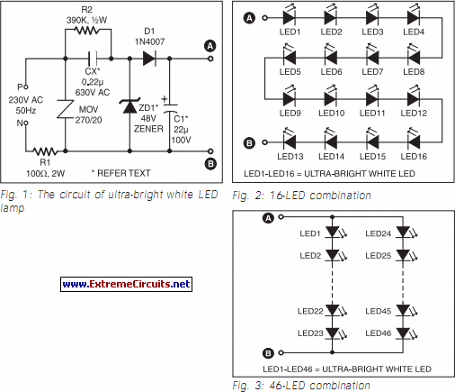
Ultra Bright LED Lamp circuit
This ultra-bright white LED lamp operates on 230V AC with low power consumption. It is suitable for illuminating VU meters, SWR meters, and similar applications. The ultra-bright LEDs available in the market range from Rs 8 to 15. These LEDs...

ALPHANUMERIC LED DISPLAY PROJECT
A tiny sandwich flag connected perpendicular to the motor spindle aids observation of how long it takes to complete one full rotation. This worked initially, as each burst from the capacitor barely moved the flag 1/4 of a rotation. As...

LED Bike Light Circuit Project
On a mountain bike, a common issue with traditional flashing LED lights from stores is the frequent problem of flat batteries and lights detaching. As an electronics student, a better solution was sought. A front wheel with a built-in dynamo...
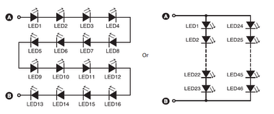
16 led46 led circuit combination
A series combination of 16 LEDs provides a luminance (lux) equivalent to a 12W bulb. However, if two series combinations of 23 LEDs are connected in parallel (totaling 46 LEDs), the output is equivalent to a 35W light bulb. Diode...
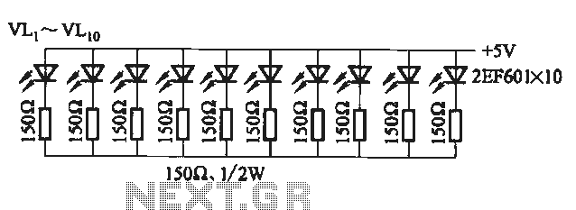
Flicker frequency of multiple sets of different light-emitting diode lights chain circuit
The circuit utilizes a 555 timer configured as a multivibrator, where the oscillation frequency is determined by resistors R1, R2, and capacitor C1. The frequency formula is given by fo = 1.443 / ((R1 + R2) * C1). The output...
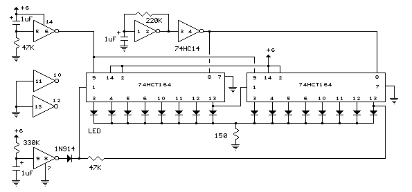
Led circuits
The circuit below illustrates powering one or two LEDs from the 120-volt AC line using a capacitor to drop the voltage and a small resistor to limit the inrush current. Since the capacitor must pass current in both directions, a...
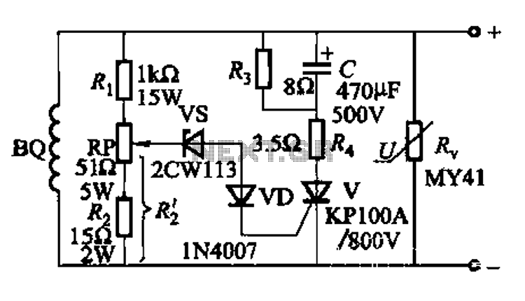
High voltage generator excitation set overvoltage protection circuit
The DC voltage for the generator field winding is supplied by a three-phase thyristor rectifier. In instances of incorrect operation, phase misalignment, or system failure, the rectifier may generate hazardous conditions, leading to over-voltage insulation issues on the DC side...
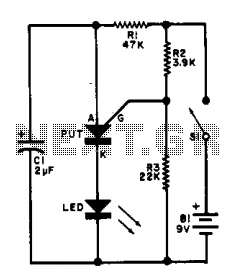
Led flasher IIV
This flasher circuit functions as a relaxation oscillator, with capacitor C1 discharging periodically through the LED when the Programmable Unijunction Transistor (PUT) is activated. The flashing rate is approximately 100 times per minute, based on the specified component values.
The flasher...
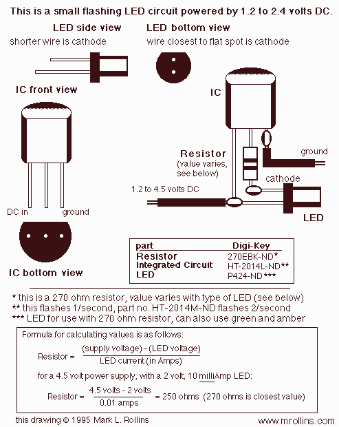
LED Blinker with HT-2014M
A very simple LED flasher circuit. With HT-2014L the circuit produces 1 flash per second and the HT-2014M produces 2 flashes per second.
The LED flasher circuit is designed to provide a visual indication through intermittent illumination of an LED. It...