


Easy fades fade switching circuit 2
#fade switching
#two-wire connection
#light control
#simple circuit
#dimmer
#LED
#lamp
#gradual fade
#switch circuit
#lighting
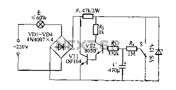
Description: This circuit is a gradual clear/fade switch for a two-wire connection, designed for simple installation. It activates the lights as needed by turning the switch dial upward. A positive supply of 2V is provided through resistor R. The capacitor (C) charges, causing the voltage across it to gradually increase, which in turn makes transistor VT2 gradually conduct. This action reduces the equivalent resistance of high-power tube VT1, causing lamp E to gradually brighten from a dark state. Once the capacitor is fully charged, the brightness of the lamp stabilizes. To turn off the lights, the switch dial is turned downward, allowing capacitor C to discharge through resistor R. This maintains the lamp's light but causes its brightness to gradually dim over time until it is completely extinguished. Resistor R1 should have a high back pressure rating, and the transistors and other components do not have special requirements.
This circuit utilizes a straightforward design to achieve a dimming effect for lighting applications. The core components include a capacitor (C), resistors (R and R1), and transistors (VT1 and VT2). The circuit operates by leveraging the charging and discharging characteristics of the capacitor to control the brightness of the lamp (E).
When the circuit is powered, the capacitor begins to charge through resistor R, resulting in a gradual increase in voltage across the capacitor. This increase influences the base of transistor VT2, allowing it to turn on progressively. As VT2 conducts, it reduces the effective resistance presented by high-power transistor VT1, which is responsible for driving the lamp. The lamp (E) thus brightens smoothly as the voltage rises, providing a visually appealing fade-in effect.
Conversely, when the switch is turned to the off position, the capacitor begins discharging through resistor R. This discharge process allows the lamp to remain lit for a brief period, but the brightness diminishes gradually as the capacitor voltage drops. The time it takes for the lamp to extinguish completely depends on the values of the capacitor and resistor used in the circuit, which can be adjusted to achieve the desired fade-out duration.
The circuit's design is robust, with no specific requirements for the transistors or other components, allowing for flexibility in component selection. The high back pressure rating for resistor R1 is crucial to ensure reliable operation under varying load conditions. Overall, this gradual clear/fade switch circuit is an effective solution for applications requiring controlled lighting transitions.End a two-wire connection gradually clear/fade switch circuit when the circuit is relatively simple to install. Turn on the lights when needed, H properly switch S dial upward, positive supply via] 2V R. The capacitor (1 charge, the C voltage across gradually increased, so make VT2 gradually step guide Annals of people, high-power tube VT1 equivalent resistance decreased, lamp E gradually brighten the dark. When the C full charge the brightness of the lamp will no longer change when you turn off the lights of the store s dial downward, C.
charge Pan R; to VT2 discharge lamp can be maintained light, but dichotoma brightness gradually darken over time, when (- charge when basic is done and the lights went completely extinguished. v r1 should be high back pressure power NI, N transistors, other components, no special requirements.
This circuit utilizes a straightforward design to achieve a dimming effect for lighting applications. The core components include a capacitor (C), resistors (R and R1), and transistors (VT1 and VT2). The circuit operates by leveraging the charging and discharging characteristics of the capacitor to control the brightness of the lamp (E).
When the circuit is powered, the capacitor begins to charge through resistor R, resulting in a gradual increase in voltage across the capacitor. This increase influences the base of transistor VT2, allowing it to turn on progressively. As VT2 conducts, it reduces the effective resistance presented by high-power transistor VT1, which is responsible for driving the lamp. The lamp (E) thus brightens smoothly as the voltage rises, providing a visually appealing fade-in effect.
Conversely, when the switch is turned to the off position, the capacitor begins discharging through resistor R. This discharge process allows the lamp to remain lit for a brief period, but the brightness diminishes gradually as the capacitor voltage drops. The time it takes for the lamp to extinguish completely depends on the values of the capacitor and resistor used in the circuit, which can be adjusted to achieve the desired fade-out duration.
The circuit's design is robust, with no specific requirements for the transistors or other components, allowing for flexibility in component selection. The high back pressure rating for resistor R1 is crucial to ensure reliable operation under varying load conditions. Overall, this gradual clear/fade switch circuit is an effective solution for applications requiring controlled lighting transitions.End a two-wire connection gradually clear/fade switch circuit when the circuit is relatively simple to install. Turn on the lights when needed, H properly switch S dial upward, positive supply via] 2V R. The capacitor (1 charge, the C voltage across gradually increased, so make VT2 gradually step guide Annals of people, high-power tube VT1 equivalent resistance decreased, lamp E gradually brighten the dark. When the C full charge the brightness of the lamp will no longer change when you turn off the lights of the store s dial downward, C.
charge Pan R; to VT2 discharge lamp can be maintained light, but dichotoma brightness gradually darken over time, when (- charge when basic is done and the lights went completely extinguished. v r1 should be high back pressure power NI, N transistors, other components, no special requirements.
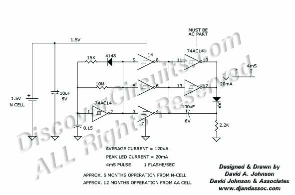
15 v led flasher schematics
Many published circuits that flash LEDs require 3 volts or more. This circuit utilizes a single inexpensive C-MOS IC and can flash an LED for an entire year on a single 1.5-volt AA alkaline battery cell. The circuit employs a...
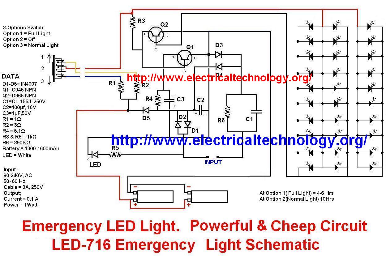
Emergency LED Light LED-716 Emergency Light Schematic
This circuit illustrates the modifications made due to a blown resistor on the backside, which was soldered in place. The issue was traced back to this specific resistor. Currently, the pattern change switch is set to Option 3, which corresponds...
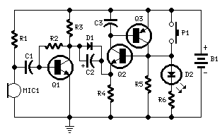
Electronic Candle Blow Out
This design was developed by request of a correspondent having made a sort of LED candle and needing to switch off the LED with a puff. This simple, easy to build gadget can be useful as a prop for Halloween...
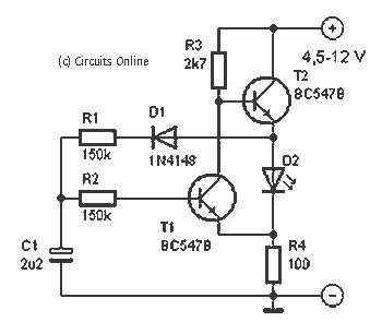
LED Flasher IIV
This is a simple design of a single flashlight. This small circuit is within a half hour to build. The circuit operates from 4.5 to 12 V. Of course it is possible other than to drive an LED. More: R1,...
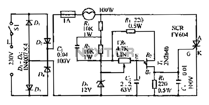
A linear dimming controller
An AC voltage of 30V is rectified. The positive terminal is connected to a fuse and a 100W bulb, while the negative terminal is connected to a thyristor. A Zener diode provides a stable bias voltage. A variable resistor (VR)...
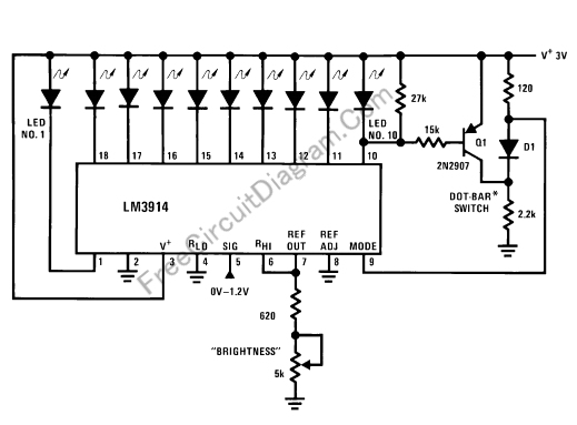
LED Audio Level (VU) Indicator and Alarm: The Dot Turns to Bar When The Signal Reach The Maximum Le
This LED (Light Emitting Diode) display consists of 10 LEDs to indicate the level of an input signal. If the signal is low, only LED #1 will light up. As the signal level increases, the illuminated dot will progress through...
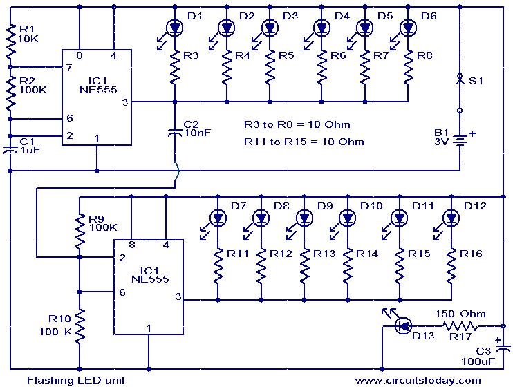
Flashing LED unit
The circuit presented is designed as an LED flasher that creates a rotating effect when the LEDs are arranged appropriately. It operates with very low current consumption and can function using 3V button cells. The first integrated circuit (IC1), a...
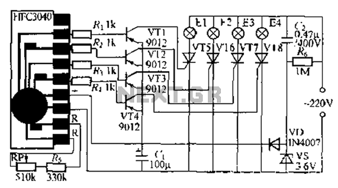
Four flashing lights string circuit 2
The circuit utilizes a four-way slowly dimming LED driver integrated with iU shoe production and a Qis four flashing lights string controller. The C3484 manifold is specifically designed to operate Ji lights with four lights that flash and slowly fade....
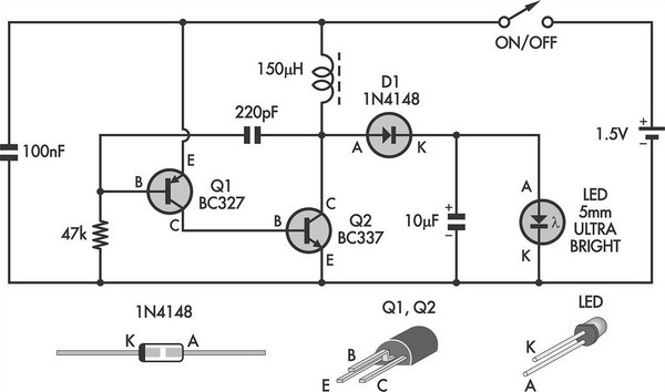
LED Torch Uses Blocking Oscillator
This simple LED torch is driven by a 2-transistor blocking oscillator that steps up the voltage from a 1.5V cell. It relies on the inherent current limiting of the 150 µH choke to protect the white LED from overdrive. With...