


Fade one lamp dimming switch circuit
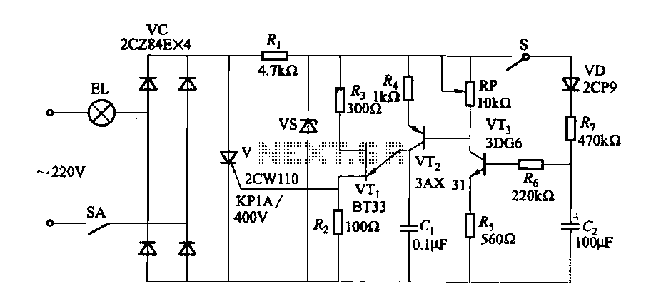
Description: A fade-in fade-out light switch enables gradual adjustments in lamp brightness, allowing the light to turn on and off smoothly. When the switch SA is closed, the lamp brightness increases from dim to bright. Conversely, when the switch SA is opened, the brightness gradually decreases from bright to off. The adjustment potentiometer RP allows for variation in bulb brightness. According to the values indicated in the accompanying figure, the fade-in and fade-out processes can take approximately 60 seconds. By modifying the components Rs, horses, cl, and the resistance of RP, the timing for the fade-in and fade-out effects can be customized. For controlling multiple lamps, it is advisable to use a high-current rectifier diode and a thyristor.
The fade-in fade-out light switch circuit is designed to create a smooth transition in lamp brightness, enhancing the user experience and providing a gentle lighting effect. The circuit typically consists of a power supply, a switch (SA), a potentiometer (RP), and components such as resistors (Rs), capacitors (cl), and possibly a thyristor for controlling higher current loads.
When the switch SA is engaged, the circuit allows current to flow, charging the capacitor cl through the resistor Rs. This charging process creates a time delay, during which the voltage across the capacitor increases gradually. As the voltage rises, the lamp connected to the circuit experiences a corresponding increase in brightness, providing a smooth fade-in effect. The rate of brightness increase can be adjusted by changing the values of Rs and cl, which determine the time constant of the circuit.
Upon opening the switch SA, the capacitor begins to discharge, causing the lamp brightness to decrease gradually. The discharge rate is also influenced by the values of Rs and the potentiometer RP, allowing for fine-tuning of the fade-out duration. The design ensures that the transition between the two states is not abrupt, thereby creating a pleasant visual effect.
For applications requiring control over multiple lamps or higher wattage lighting, the circuit can incorporate a high-current rectifier diode to handle the increased load. Additionally, a thyristor can be utilized to provide more robust control over the power delivered to the lamps, ensuring reliable operation under varying conditions.
Overall, this circuit design provides a versatile solution for controlling lamp brightness with smooth transitions, suitable for various lighting applications in residential and commercial settings.Fade-in fade-out light switch can turn on and off when the lamp brightness changes slowly, and the brightness can be adjusted. (1) One of fade-dimming lamp switch circuit circu it shown in Figure 2-35. When closing the switch SA, the lamp brightness from weak to strong light; open the switch SA, lamp brightness from strong to weak extinguished. Adjustment potentiometer RP, can change the bulb. Such as using the values shown in Figure 2-35, lights fade in, fade-out process of approximately 60s.
Change Rs, horses, cl, and the resistance of RP, you can adjust the fade in, fade-out time. If you want to control the lamp power group, select high current rectifier diode and thyristor can be.
The fade-in fade-out light switch circuit is designed to create a smooth transition in lamp brightness, enhancing the user experience and providing a gentle lighting effect. The circuit typically consists of a power supply, a switch (SA), a potentiometer (RP), and components such as resistors (Rs), capacitors (cl), and possibly a thyristor for controlling higher current loads.
When the switch SA is engaged, the circuit allows current to flow, charging the capacitor cl through the resistor Rs. This charging process creates a time delay, during which the voltage across the capacitor increases gradually. As the voltage rises, the lamp connected to the circuit experiences a corresponding increase in brightness, providing a smooth fade-in effect. The rate of brightness increase can be adjusted by changing the values of Rs and cl, which determine the time constant of the circuit.
Upon opening the switch SA, the capacitor begins to discharge, causing the lamp brightness to decrease gradually. The discharge rate is also influenced by the values of Rs and the potentiometer RP, allowing for fine-tuning of the fade-out duration. The design ensures that the transition between the two states is not abrupt, thereby creating a pleasant visual effect.
For applications requiring control over multiple lamps or higher wattage lighting, the circuit can incorporate a high-current rectifier diode to handle the increased load. Additionally, a thyristor can be utilized to provide more robust control over the power delivered to the lamps, ensuring reliable operation under varying conditions.
Overall, this circuit design provides a versatile solution for controlling lamp brightness with smooth transitions, suitable for various lighting applications in residential and commercial settings.Fade-in fade-out light switch can turn on and off when the lamp brightness changes slowly, and the brightness can be adjusted. (1) One of fade-dimming lamp switch circuit circu it shown in Figure 2-35. When closing the switch SA, the lamp brightness from weak to strong light; open the switch SA, lamp brightness from strong to weak extinguished. Adjustment potentiometer RP, can change the bulb. Such as using the values shown in Figure 2-35, lights fade in, fade-out process of approximately 60s.
Change Rs, horses, cl, and the resistance of RP, you can adjust the fade in, fade-out time. If you want to control the lamp power group, select high current rectifier diode and thyristor can be.
Lamp remote control circuit
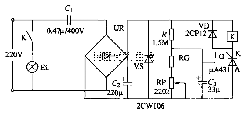
The circuit utilizes a 220V AC voltage input that is processed through a capacitor (C1) for bucking, followed by a rectifier bridge (UR) which acts as a barrier-wave rectifier. A filter capacitor (C2) is used to smooth the output voltage...
AMP Hexadecimal Rotary Switch
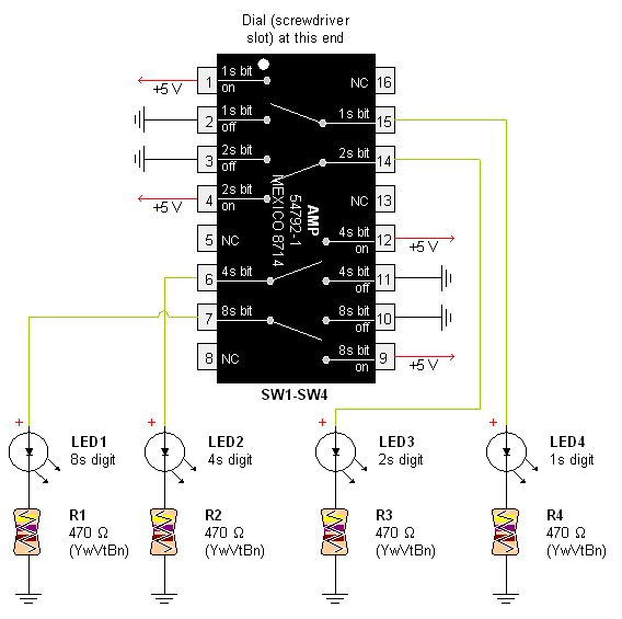
Pictures and a sample schematic (including pinouts) of an AMP hexadecimal (16-position) switch with a screw slot actuator.
The AMP hexadecimal switch is a 16-position rotary switch designed for applications requiring multiple selectable options. This switch features a screw slot actuator...
Schematic Diagram for Model 350 PAFN
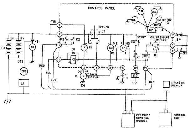
When both S1 and R2 are activated, current flows through each of the lamps connected in parallel to the rheostat. The current flow, and consequently the intensity of illumination, can be regulated by adjusting the effective voltage from the batteries,...
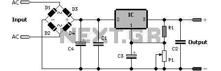
Adjustable 1.5 - 35 V DC Regulated Power Supply Circuit
Adjustable 1.5 - 35 V DC Regulated Power Supply Circuit Diagram. This diagram includes three circuit designs and is categorized under Power Supply. For more information, refer to the detailed post titled "Adjustable 1.5 - 35 V DC Regulated Power...
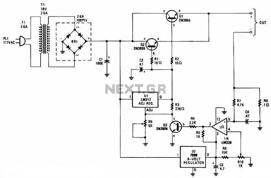
Adjustable Regulated Battery Charger
This battery charger circuit is regulated and adjustable, enabling it to charge most NiCAD batteries. It is suitable for single cells or multiple battery cells connected in series or parallel configurations. The maximum...
This battery charger circuit is designed to provide...
AMP Hexadecimal Rotary Switch
Pictures and a sample schematic (including pinouts) of an AMP hexadecimal (16-position) switch with a screw slot actuator.
The AMP hexadecimal switch is a 16-position rotary switch designed for applications requiring multiple selectable options. This switch features a screw slot actuator...
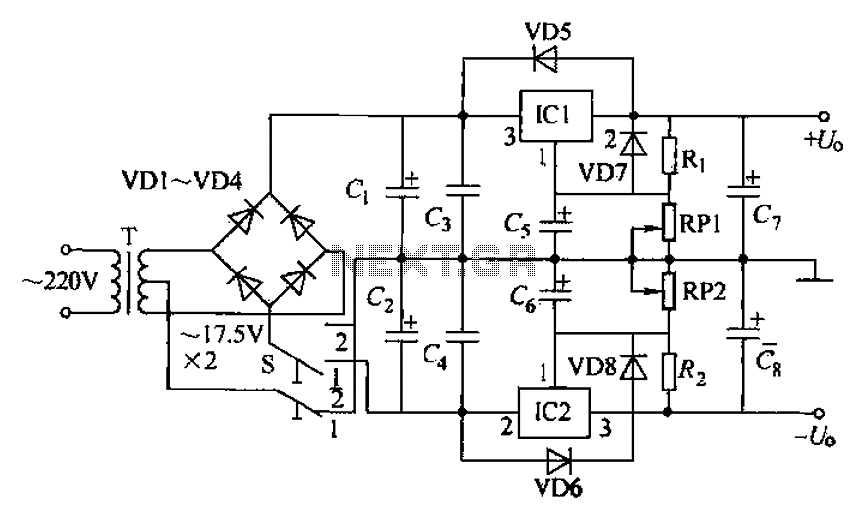
Dual adjustable power supply circuit
The circuit utilizes a three-terminal adjustable integrated voltage regulator. It includes a gear set and a power supply voltage that is stepped down using a transformer rated at 17.5V x 2 AC. The output voltage after the bridge rectifier is...
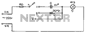
Simple dimming lights circuit diagram
The figure illustrates a basic dimming lights circuit. The light intensity is controlled by a multi-speed control switch, designated as K. When switch K is set to position "1," the lights are turned off. In position "2," the light emits...
automatic room light controller with
The objective of this project is to create a controller-based model that counts the number of individuals entering a specific room and activates the lighting accordingly. A sensor will be utilized to determine the current number of persons present. In...