


Fade or gradually eliminate style lighting controller circuit
#lighting controller
#fade effect
#gradual brightness
#LED
#inrush current reduction
#human eye protection
#dimmer
#soft start
#lighting automation
#PWM
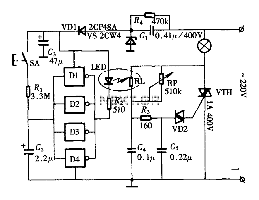
Description: The lighting controller depicted in the figure features a gradual dimming function that prevents sudden brightness changes, which can irritate the human eye and potentially cause damage due to inrush currents. The circuit design includes a six-stage CD4069 inverter configuration, which is complemented by a photo-coupler light-emitting diode driving circuit. To enhance the circuit's driving capability, four inverters are arranged in parallel.
The lighting controller circuit is designed to provide a smooth transition in light intensity, thereby minimizing abrupt changes that could lead to discomfort or harm. The use of a CD4069 inverter, known for its versatility in logic applications, allows for effective signal inversion and control within the circuit. The integration of a photo-coupler ensures electrical isolation between the control and load circuits, enhancing safety and performance.
The parallel arrangement of four inverters significantly increases the current handling capability of the circuit, making it suitable for driving higher power loads without compromising performance. This configuration effectively distributes the load across multiple inverters, reducing the risk of overheating and failure.
In practical applications, this lighting controller can be utilized in various environments, including residential lighting, stage lighting, and automotive lighting systems, where gradual illumination is preferred. The circuit's ability to manage inrush current effectively protects both the lamps and the associated circuitry, extending the lifespan of the components and improving overall reliability. This design not only enhances user comfort but also contributes to energy efficiency by allowing for controlled light output based on ambient conditions.As shown in FIG lighting controller with lights getting brighter gradually eliminate function, which can make the lights do not appear when the lights suddenly brighten the human eye irritation and damage the inrush current can be reduced when the lights may cause the lamp, circuit as shown in FIG. The circuit consists of a six-foot CD4069 inverter circuit composed of photo-coupler light emitting diode driving circuit, in order to enhance the driving ability of the circuit, four inverters in parallel. " alt="Fade, gradually eliminate style lighting controller circuit">
The lighting controller circuit is designed to provide a smooth transition in light intensity, thereby minimizing abrupt changes that could lead to discomfort or harm. The use of a CD4069 inverter, known for its versatility in logic applications, allows for effective signal inversion and control within the circuit. The integration of a photo-coupler ensures electrical isolation between the control and load circuits, enhancing safety and performance.
The parallel arrangement of four inverters significantly increases the current handling capability of the circuit, making it suitable for driving higher power loads without compromising performance. This configuration effectively distributes the load across multiple inverters, reducing the risk of overheating and failure.
In practical applications, this lighting controller can be utilized in various environments, including residential lighting, stage lighting, and automotive lighting systems, where gradual illumination is preferred. The circuit's ability to manage inrush current effectively protects both the lamps and the associated circuitry, extending the lifespan of the components and improving overall reliability. This design not only enhances user comfort but also contributes to energy efficiency by allowing for controlled light output based on ambient conditions.As shown in FIG lighting controller with lights getting brighter gradually eliminate function, which can make the lights do not appear when the lights suddenly brighten the human eye irritation and damage the inrush current can be reduced when the lights may cause the lamp, circuit as shown in FIG. The circuit consists of a six-foot CD4069 inverter circuit composed of photo-coupler light emitting diode driving circuit, in order to enhance the driving ability of the circuit, four inverters in parallel. " alt="Fade, gradually eliminate style lighting controller circuit">
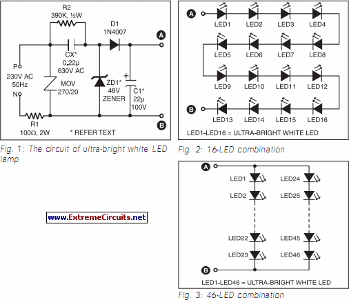
Ultra Bright LED Lamp circuit
This ultra-bright white LED lamp operates on 230V AC with low power consumption. It is suitable for illuminating VU meters, SWR meters, and similar applications. The ultra-bright LEDs available in the market range from Rs 8 to 15. These LEDs...
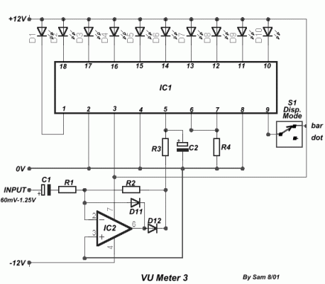
VU Meter 3
A very simple circuit for indicating levels, utilizing 10 LEDs. The circuit employs a precision half-wave rectification around the IC2, with a gain of one. The switch S1 allows for the selection of which LED to indicate. The input level...
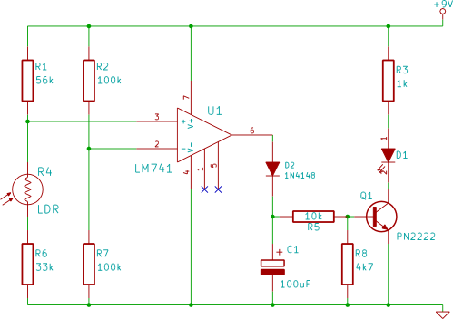
automatic light
This electronic breadboard circuit for beginners in electronics activates an LED automatically when the ambient light level falls below a specific threshold.
This circuit utilizes a light-dependent resistor (LDR) as the primary sensor to detect ambient light levels. The LDR is...
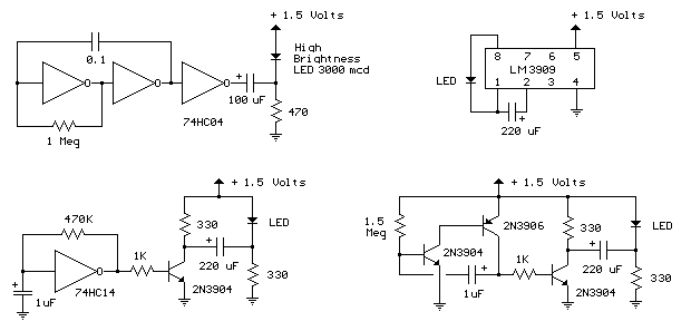
1.5 Volt LED Flasher Circuits
The LED flasher circuits below operate on a single 1.5 volt battery. The circuit on the upper right uses the popular LM3909 LED flasher IC and requires only a timing capacitor and LED. The top left circuit, designed by Andre...
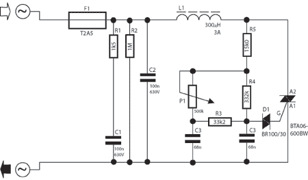
simple dimmer circuit
A potentiometer regulates the firing point of the triac. Capacitor C4 is charged through resistors R3, R4, P1, and R5. After a specific duration, determined by the potentiometer setting, the charge in C4 becomes sufficient for the diac D to...
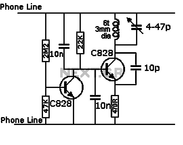
low cost precision light control dimmer
This circuit utilizes a controlled half-plus fixed half-wave phase control method to regulate an 860-watt lamp load, allowing for power adjustment from half to full capacity. The circuit controls the light output of the lamp, enabling a range from 30%...
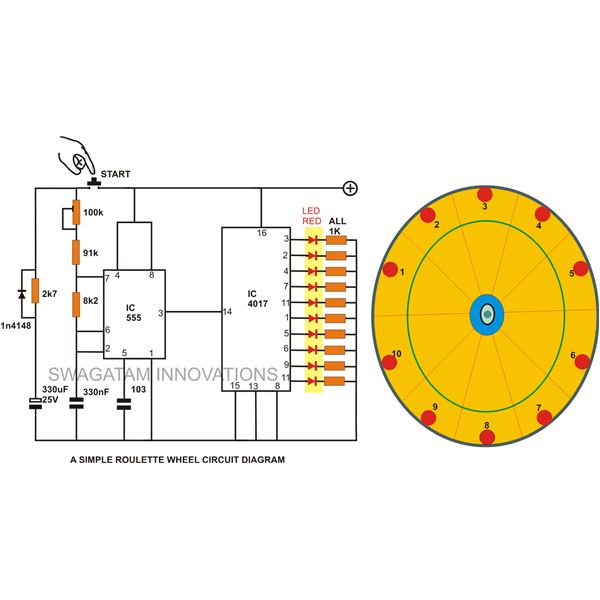
10 led simple roulette wheel circuit
A simple circuit for a 10 LED roulette wheel is presented. Pressing the button initiates the LEDs in a rotational sequence that starts at full speed and gradually decelerates until it halts at a randomly selected LED. The randomness of...
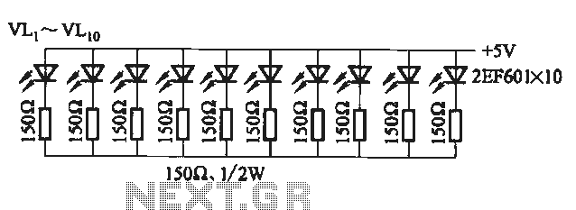
Flicker frequency of multiple sets of different light-emitting diode lights chain circuit
The circuit utilizes a 555 timer configured as a multivibrator, where the oscillation frequency is determined by resistors R1, R2, and capacitor C1. The frequency formula is given by fo = 1.443 / ((R1 + R2) * C1). The output...
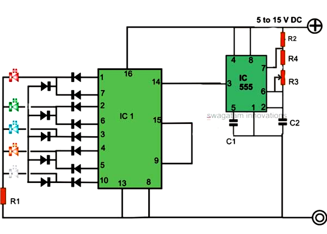
How to Make a Simple Reverse Forward LED Light Chaser Circuit Using IC 4017
An LED light chaser circuit is an electronic configuration designed to illuminate a group of LEDs in a predetermined sequence. A commonly used integrated circuit (IC) for creating this type of LED sequencer circuit is the 4017. This IC functions...