


Flasher and Fader LED Circuit Using IC 555
Description: The astable multivibrator mode is the most basic operational mode of the IC 555. In this mode, it functions as a free-running oscillator. When the oscillator rate is sufficiently reduced, it can be used to drive LED lights. The output wiring can also be modified to achieve various interesting illumination patterns with the connected LED. Practical implementations include circuit diagrams for LED flashers, ghost effect generators, alternate blinkers, and light faders. This article discusses several simple LED blinker circuit configurations utilizing the versatile IC 555. The basic flashing mode remains intact while various modifications are made to the circuit's flashing rate and pattern. The IC 555 serves as a comprehensive tool for hobbyists, enabling the construction of numerous interesting circuits that can operate in various ways. Although the circuit supports a wide range of applications, flasher configurations are commonly associated with this chip. It can be used to blink various types of lights at different rates based on individual preferences. LEDs, torch bulbs, string lights, or even mains AC lamps can be flashed using circuits that incorporate this IC. To configure the IC as a flasher or blinker, it is connected in its fundamental astable multivibrator mode, which requires only a couple of resistors and capacitors to initiate the desired functions. Once the chip is set up as an astable multivibrator, the output can be enhanced in various ways to produce captivating visual effects.
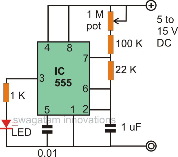
To begin, hobbyists should gather a collection of assorted resistors and selected values of capacitors for these projects. The basic configuration associated with the 555 IC, shown in the first figure, connects it as an astable multivibrator. The resistors and a 1 µF capacitor can be varied to achieve different blinking rates for the connected LED. LEDs of various colors can also be utilized. The circuit can be modified to produce a revolving, flashing police light effect by adding a network of a zener diode, resistor, and capacitor to the output. This modification generates a unique illumination effect where the LED initially glows brightly, then slowly dims, while intermittently producing a high-intensity pulse that simulates a police warning light.
The configuration illustrated enables the generation of random light patterns across a connected group of LEDs. In this setup, three LEDs are connected with a couple of resistors and a capacitor. Two LEDs, connected in parallel but with opposite polarity, flash alternately at a specific rhythm, while the third LED fluctuates at a different random rate. This effect can be simplified in another circuit where one LED, connected to a 1 kΩ resistor, blinks at a fixed rate, while another LED connected to ground switches rapidly at a different defined rate. To create unique illumination patterns with the discussed circuits, a couple of resistors can be connected at the output of the IC in a specific arrangement. This network allows the LED to switch ON sharply while switching OFF slowly, producing intriguing visual effects.The astable multivibrator mode is the most fundamental mode of operation of the IC 555. In this mode it basically functions like a free running oscillator. If this oscillator rate is reduced sufficiently, can be used for driving LED lights. The wiring at the output can also be further modified for achieving interesting variations and light ill umination patterns over the connected LED. Some of the practical ways of this is explained here, circuits diagrams of LED flasher, ghost effect generator, alternate blinker, light fader etc are also included. The article explains a few interesting and simple LED blinker circuit configurations using the ubiquitous IC 555.
The basic flashing mode has been kept intact yet various different attributions are provided to the circuit with its flashing rate and pattern. The IC 555 is a complete package for the hobbyists. You can build numerous interesting circuits with this chip and make it to work as virtually any way you desire.
Though the circuit provides us with many application ranges, flashers configurations are more commonly associated with these chips. These can be made to blink all types of lights at different rates depending upon individual preferences.
You can flash LEDs, torch bulbs, string lights or even mains AC lamps with circuits incorporating this IC. Basically, to configure the IC as a flasher or blinker, it`s connected with its fundamental astable mutivibrator mode.
This configuration in fact requires just a couple of resistors and a couple capacitors to kick start the said functions. Once the chip is assembled as an astable, we can go ahead and enhance the output in many different ways to get outstanding visual treats.
Let`s learn how a few fabulous IC 555 circuits with LED can be built with the following discussions, but first we would like to know what materials are needed for this. Being a hobbyist you would want to have a bunch of assorted resistors in your box of goodies and also some selected values of capacitors.
For the present projects you would require a handful of different value resistors and capacitors. The first figure shows the basic configuration associated with 555 ICs, here it is connected as an astable multivibrator. The resistors and the capacitor 1 uF can be experimented with to get different rates of blinking over the connected LED.
The LEDs can also be used with oter colors. The above circuit can be suitably modified for producing a revolving, flashing police light effect to the above constructed circuit. Here by adding a network of a zener diode / resistor / capacitor, to the output of the circuit, just as shown in the figure, we can acquire a very peculiar effect with the generated illuminations of the LED.
The LED initially glows bright, then slowly dies down, but intermittently gives a high intensity pulse producing the discussed police warning roof light indicator illusion. The configuration shown in this figure enables us to use the circuit to generate random light patterns over the connected group of LEDs.
As shown, three LEDs are connected in conjunction with a couple of resistors and a capacitor. The two LEDs connected in parallel but with opposite polarity, flasg alternately at a particular rhythm while the third LED fluctuates at some other random rate. The above effect can be simplified by the circuit shown below. Here, the LED which is connected to the 1 K resistor blinks at the fixed blinking rate, but the next LED which is connected to the ground switches rapidly at some other defined rate.
If you want to produce some strange illumination pattern over the LED discussed through the above circuits, them it can be simply done using just a couple of resistors at the output of the IC. As can be seen in the figure, two resistors and a single resistor are connected at the output of the IC in a special way.
The network switches ON the LED sharply, but switches it OFF slowly, producing
To begin, hobbyists should gather a collection of assorted resistors and selected values of capacitors for these projects. The basic configuration associated with the 555 IC, shown in the first figure, connects it as an astable multivibrator. The resistors and a 1 µF capacitor can be varied to achieve different blinking rates for the connected LED. LEDs of various colors can also be utilized. The circuit can be modified to produce a revolving, flashing police light effect by adding a network of a zener diode, resistor, and capacitor to the output. This modification generates a unique illumination effect where the LED initially glows brightly, then slowly dims, while intermittently producing a high-intensity pulse that simulates a police warning light.
The configuration illustrated enables the generation of random light patterns across a connected group of LEDs. In this setup, three LEDs are connected with a couple of resistors and a capacitor. Two LEDs, connected in parallel but with opposite polarity, flash alternately at a specific rhythm, while the third LED fluctuates at a different random rate. This effect can be simplified in another circuit where one LED, connected to a 1 kΩ resistor, blinks at a fixed rate, while another LED connected to ground switches rapidly at a different defined rate. To create unique illumination patterns with the discussed circuits, a couple of resistors can be connected at the output of the IC in a specific arrangement. This network allows the LED to switch ON sharply while switching OFF slowly, producing intriguing visual effects.The astable multivibrator mode is the most fundamental mode of operation of the IC 555. In this mode it basically functions like a free running oscillator. If this oscillator rate is reduced sufficiently, can be used for driving LED lights. The wiring at the output can also be further modified for achieving interesting variations and light ill umination patterns over the connected LED. Some of the practical ways of this is explained here, circuits diagrams of LED flasher, ghost effect generator, alternate blinker, light fader etc are also included. The article explains a few interesting and simple LED blinker circuit configurations using the ubiquitous IC 555.
The basic flashing mode has been kept intact yet various different attributions are provided to the circuit with its flashing rate and pattern. The IC 555 is a complete package for the hobbyists. You can build numerous interesting circuits with this chip and make it to work as virtually any way you desire.
Though the circuit provides us with many application ranges, flashers configurations are more commonly associated with these chips. These can be made to blink all types of lights at different rates depending upon individual preferences.
You can flash LEDs, torch bulbs, string lights or even mains AC lamps with circuits incorporating this IC. Basically, to configure the IC as a flasher or blinker, it`s connected with its fundamental astable mutivibrator mode.
This configuration in fact requires just a couple of resistors and a couple capacitors to kick start the said functions. Once the chip is assembled as an astable, we can go ahead and enhance the output in many different ways to get outstanding visual treats.
Let`s learn how a few fabulous IC 555 circuits with LED can be built with the following discussions, but first we would like to know what materials are needed for this. Being a hobbyist you would want to have a bunch of assorted resistors in your box of goodies and also some selected values of capacitors.
For the present projects you would require a handful of different value resistors and capacitors. The first figure shows the basic configuration associated with 555 ICs, here it is connected as an astable multivibrator. The resistors and the capacitor 1 uF can be experimented with to get different rates of blinking over the connected LED.
The LEDs can also be used with oter colors. The above circuit can be suitably modified for producing a revolving, flashing police light effect to the above constructed circuit. Here by adding a network of a zener diode / resistor / capacitor, to the output of the circuit, just as shown in the figure, we can acquire a very peculiar effect with the generated illuminations of the LED.
The LED initially glows bright, then slowly dies down, but intermittently gives a high intensity pulse producing the discussed police warning roof light indicator illusion. The configuration shown in this figure enables us to use the circuit to generate random light patterns over the connected group of LEDs.
As shown, three LEDs are connected in conjunction with a couple of resistors and a capacitor. The two LEDs connected in parallel but with opposite polarity, flasg alternately at a particular rhythm while the third LED fluctuates at some other random rate. The above effect can be simplified by the circuit shown below. Here, the LED which is connected to the 1 K resistor blinks at the fixed blinking rate, but the next LED which is connected to the ground switches rapidly at some other defined rate.
If you want to produce some strange illumination pattern over the LED discussed through the above circuits, them it can be simply done using just a couple of resistors at the output of the IC. As can be seen in the figure, two resistors and a single resistor are connected at the output of the IC in a special way.
The network switches ON the LED sharply, but switches it OFF slowly, producing

Implementing Adaptive Brightness Control to Seven Segment LED Displays
An automatic brightness adjustment is a closed-loop system that has the capability to assess ambient light and adjust the brightness of the display accordingly.
The automatic brightness adjustment circuit operates by utilizing a light sensor, typically a photoresistor (LDR) or photodiode,...
A Tan Timer Circuit
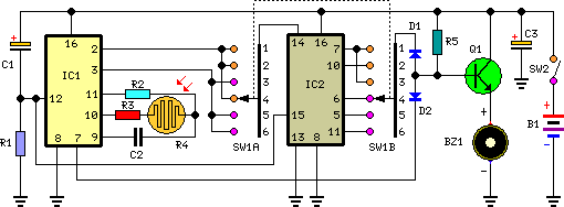
This timer is designed for individuals seeking to achieve a tan while minimizing excessive exposure to sunlight. A rotary switch allows the user to set the timer based on six classified photo-types. A photoresistor adjusts the preset time value in...

Ultra Bright LED Lamp
This ultra-bright white LED lamp operates on 230V AC with minimal power consumption. It is suitable for illuminating VU meters, SWR meters, and similar applications.
The ultra-bright white LED lamp designed for 230V AC operation offers significant advantages in terms of...

High-intensity LED Warning Flasher
This circuit was designed as a warning flasher to alert road users to dangerous situations in the dark. Alternatively, it can act as a bicycle light.
The circuit operates by utilizing a light-emitting diode (LED) as the primary visual alerting component....
How does LED Flashes One by One in my Project Some Queries
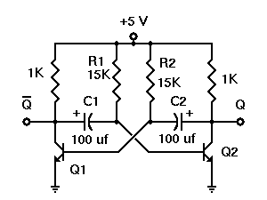
A project called LED Flasher that sequentially flashes LEDs one by one. There is a query regarding the project, and any simple explanation would be greatly appreciated. A reference image or a link can be used for additional context.
The LED...
LC CHECKER
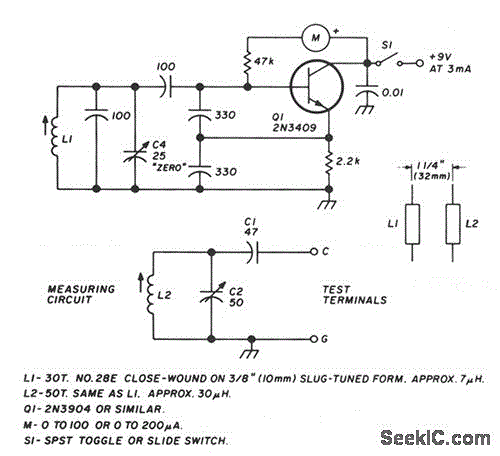
The circuit operates on the principle of the grid-dip or absorption effect, which takes place when a parallel resonant circuit is coupled to an oscillator operating at the same frequency. Transistor Q1 functions within a standard Colpitts oscillator circuit, maintaining...

LED pulse width modulator
Early in the exploration of high-power LEDs, such as the Luxeon 1 and 3-watt devices, the potential of Pulse Width Modulation (PWM) techniques for LED modulation was considered. This method theoretically minimizes distortion by making the LED's "Current versus Luminous...
Supply Voltage Indicator
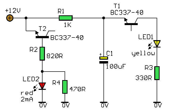
This circuit clearly indicates the supply voltage level in a larger device. When the indicator receives a stable 12 volts, LED1 emits a steady yellow light. If the input voltage drops below 11 volts, LED1 begins to blink, with the...
Automatic LED Emergency Light Circuit
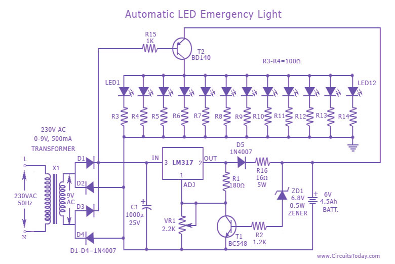
This is a cost-effective and straightforward emergency light circuit developed for CircuitsToday. It is an automatic emergency lamp with daylight sensing capabilities, meaning it detects darkness and turns on automatically, while also sensing daylight to turn off. The circuit does...