


Flashing Lamps
#flashing lamps
#Christmas tree lights
#SCR
#transistor
#timing circuit
#capacitor
#resistors
#trigger circuit

Description: This circuit is intended as a reliable replacement to thermally-activated switches used for Christmas tree lamp-flashing. The device formed by Q1, Q2 and related resistors triggers the SCR. Timing is provided by R1, R2 & C1. To change flashing frequency do not modify R1 and R2 values: set C1 value from 100 to 2200µF instead. More: Best performances are obtained with C1= 470 or 1000µF and R4= 12K or 10K. Due to low consumption of normal 10 or 20 lamp series-loops intended for Christmas trees (60mA @ 230V typical for a 20 lamp series-loop), very small and cheap SCR devices can be used.
The circuit operates as a lamp-flashing controller designed specifically for use with Christmas tree lighting systems. It utilizes a silicon-controlled rectifier (SCR) to manage the on-off switching of the lights. The primary components involved in the operation include two transistors (Q1, Q2), resistors (R1, R2, R4), and a capacitor (C1).
The timing mechanism of the circuit is crucial for determining the flash frequency of the lamps. R1 and R2 act as biasing resistors for the transistors, while C1 serves as a timing capacitor. The value of C1 can be adjusted between 100µF and 2200µF to change the flash rate without altering R1 and R2, which allows for flexibility in operation. It is recommended to use C1 at values of either 470µF or 1000µF to achieve optimal performance, along with R4 set to either 10K or 12K ohms.
The circuit is designed to work efficiently with low power consumption typical of Christmas tree light setups, which generally draw around 60mA at 230V for a series loop of 20 lamps. This low current requirement allows for the use of compact and cost-effective SCR devices, making the circuit both an economical and space-saving solution for decorative lighting applications. The overall design ensures reliable operation while providing the desired aesthetic effect of flashing lights during the holiday season.This circuit is intended as a reliable replacement to thermally-activated switches used for Christmas tree lamp-flashing. The device formed by Q1, Q2 and related resistors triggers the SCR. Timing is provided by R1, R2 & C1. To change flashing frequency do not modify R1 and R2 values: set C1 value from 100 to 2200µF instead.
Best performances are obtained with C1= 470 or 1000µF and R4= 12K or 10K. Due to low consumption of normal 10 or 20 lamp series-loops intended for Christmas trees (60mA @ 230V typical for a 20 lamp series-loop), very small and cheap SCR devices can be
The circuit operates as a lamp-flashing controller designed specifically for use with Christmas tree lighting systems. It utilizes a silicon-controlled rectifier (SCR) to manage the on-off switching of the lights. The primary components involved in the operation include two transistors (Q1, Q2), resistors (R1, R2, R4), and a capacitor (C1).
The timing mechanism of the circuit is crucial for determining the flash frequency of the lamps. R1 and R2 act as biasing resistors for the transistors, while C1 serves as a timing capacitor. The value of C1 can be adjusted between 100µF and 2200µF to change the flash rate without altering R1 and R2, which allows for flexibility in operation. It is recommended to use C1 at values of either 470µF or 1000µF to achieve optimal performance, along with R4 set to either 10K or 12K ohms.
The circuit is designed to work efficiently with low power consumption typical of Christmas tree light setups, which generally draw around 60mA at 230V for a series loop of 20 lamps. This low current requirement allows for the use of compact and cost-effective SCR devices, making the circuit both an economical and space-saving solution for decorative lighting applications. The overall design ensures reliable operation while providing the desired aesthetic effect of flashing lights during the holiday season.This circuit is intended as a reliable replacement to thermally-activated switches used for Christmas tree lamp-flashing. The device formed by Q1, Q2 and related resistors triggers the SCR. Timing is provided by R1, R2 & C1. To change flashing frequency do not modify R1 and R2 values: set C1 value from 100 to 2200µF instead.
Best performances are obtained with C1= 470 or 1000µF and R4= 12K or 10K. Due to low consumption of normal 10 or 20 lamp series-loops intended for Christmas trees (60mA @ 230V typical for a 20 lamp series-loop), very small and cheap SCR devices can be
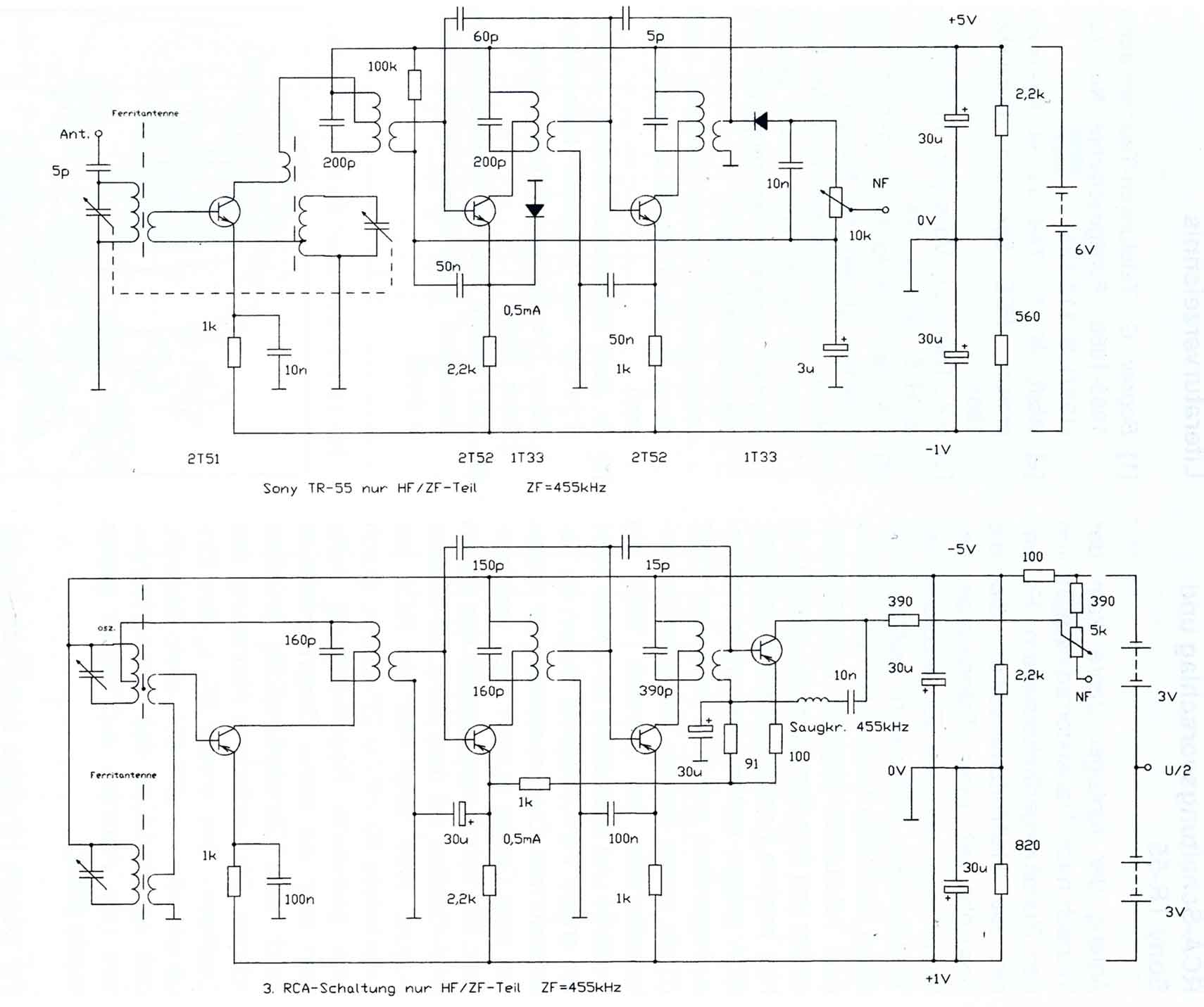
Comments on the Circuits of the first Transistor Radios
The circuitry of the Regency exhibits several unique characteristics. Notable features include the self-oscillating mixer stage, the base bias voltage of the second IF stage derived from the AF power stage, an unusual IF frequency of 262 kHz, and a...
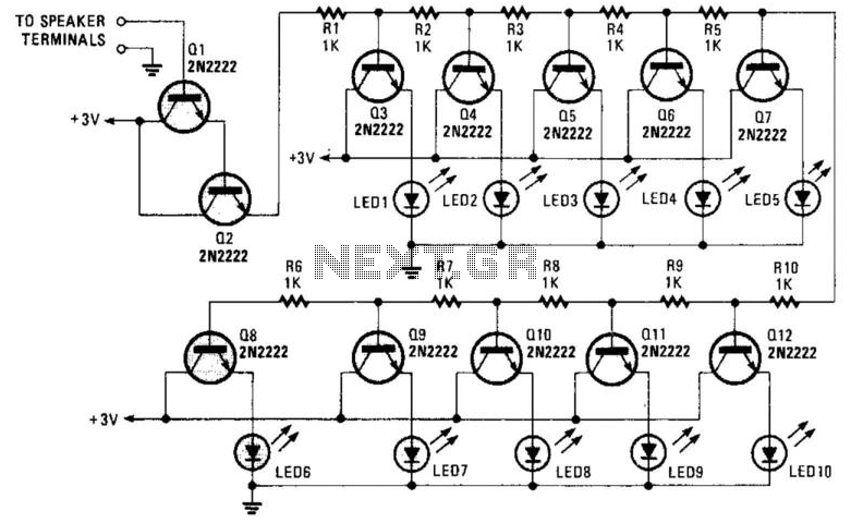
Transistorized Bar-Graph Driver
A resistor network (R1 through R10) with emitter followers (Q1 and Q2) drives LED drivers (Q3 through Q7). This circuit was utilized as a "light organ" to provide visual volume indication. It can be connected to a speaker, another audio...
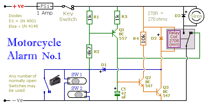
A Transistor Based Motorcycle Alarm circuit
This circuit includes a timed output and an automatic reset feature. It can be manually operated using a key switch or a concealed switch. By incorporating an external relay, the circuit will automatically engage or immobilize the machine each time...
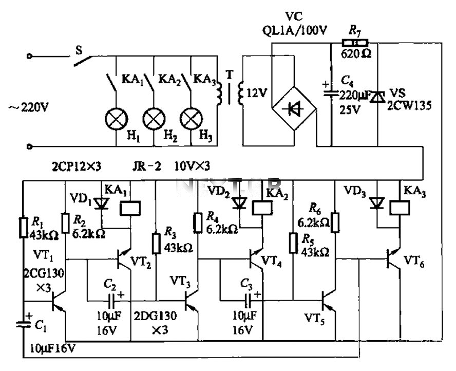
Alternately flashing lights chain multiple sets of high-power circuit 2
The transistors VTi, VT3, and VTs, along with the RC components, form three distinct multi-resonator oscillators. The oscillation frequency levels are dependent on the values of Ri, R3, Rs, and Cl, as well as Cz and C3s.
The circuit comprises three...
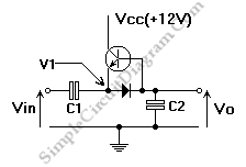
One Transistor Pump Building Block
This is a single transistor pump circuit. It is a straightforward circuit that is quite useful and can serve as a foundational component for designing more complex electronic systems.
The single transistor pump circuit utilizes a transistor as the primary active...
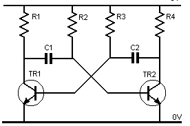
transistor astable multivibrator
Assume one of the transistors, TR1, becomes conductive initially. Under this condition, the collector-emitter voltage of TR1 should ideally be zero; however, it will be approximately 0.1 volts, while the base-emitter voltage is +0.6 volts. As a result, capacitor C1...
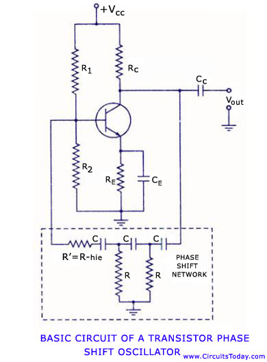
Transistor phase shift oscillator. RC phase shift network and RC phase shift oscillator using opap
Transistor RC phase shift oscillator. RC phase shift oscillator using operational amplifier. RC phase shift network. Theory and working principle. Circuit diagram.
The transistor RC phase shift oscillator is a type of electronic oscillator that generates sine wave signals. This oscillator...
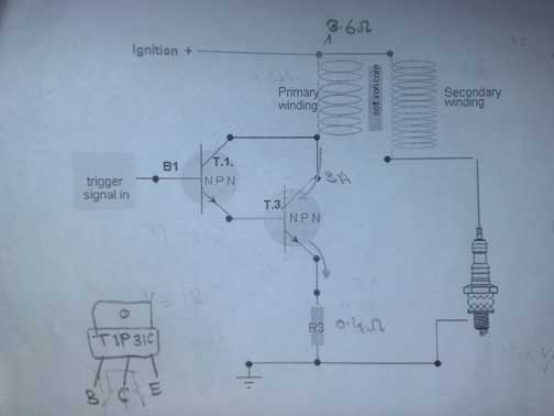
transistor ignition shematic 3
A request for assistance has been made regarding the development of a transistor ignition system to replace the point breaker in a motorcycle. The individual has researched extensively online but has not found a simple and effective circuit. The available...
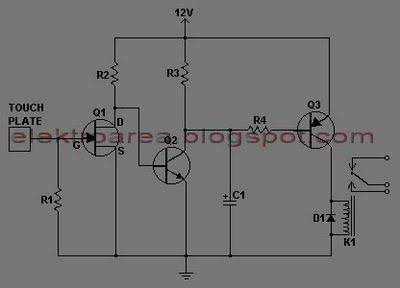
touch switch circuit with 3 transistors
This document describes a series of touch switches that utilize only three transistors. These touch-based transistor switches can activate a load simply by the user touching a metal plate. They are designed to directly switch a relay, enabling operation with...