


Floodlamp power control
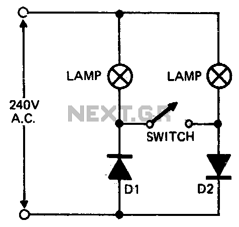
Description: When setting up photographic floodlamps, it is sometimes desirable to operate the lamps at lower power levels until actually ready to take the photograph. The circuit allows the lamps to operate on half-cycle power when the switch is open and full power when the switch is closed. The diodes D1 and D2 should have a 400-volt peak inverse voltage (PI-V) rating at 5 amps.
The described circuit is designed for controlling the power output to photographic floodlamps, providing flexibility in operation mode. In the open switch state, the circuit operates in half-cycle mode, effectively reducing the power supplied to the lamps. This is particularly useful during setup, allowing users to adjust positioning and lighting without exposing the photographic subject to full intensity light. When the switch is closed, the circuit transitions to full power mode, enabling the floodlamps to emit their maximum brightness for the actual photography.
The circuit employs two diodes, D1 and D2, which are critical for rectifying the AC supply to the floodlamps. The specified diodes must have a peak inverse voltage (PI-V) rating of at least 400 volts to withstand the voltage spikes that may occur in the circuit. Additionally, they should be rated for a forward current of 5 amps to ensure they can handle the operational current without overheating or failing.
The switch used in the circuit should be rated for the same voltage and current levels to ensure safe operation. The design may also include fuses or circuit breakers to protect against overload conditions. Proper heat dissipation measures, such as heat sinks for the diodes, may be necessary to maintain reliability and longevity of the components.
Overall, this circuit design provides a practical solution for photographers requiring control over their lighting setup, ensuring both versatility and safety during the operation of high-intensity floodlamps.When setting up photographic floodlamps, it is sometimes desirable to operate the lamps at lower power levels until actually ready to take the photograph. The circuit allows the lamps to operate on half cycle power when the switch is open, and full power, when the switch is closed
The diodes D1 and D2 should have a 400 volt PI-V rating at 5 amps.
The described circuit is designed for controlling the power output to photographic floodlamps, providing flexibility in operation mode. In the open switch state, the circuit operates in half-cycle mode, effectively reducing the power supplied to the lamps. This is particularly useful during setup, allowing users to adjust positioning and lighting without exposing the photographic subject to full intensity light. When the switch is closed, the circuit transitions to full power mode, enabling the floodlamps to emit their maximum brightness for the actual photography.
The circuit employs two diodes, D1 and D2, which are critical for rectifying the AC supply to the floodlamps. The specified diodes must have a peak inverse voltage (PI-V) rating of at least 400 volts to withstand the voltage spikes that may occur in the circuit. Additionally, they should be rated for a forward current of 5 amps to ensure they can handle the operational current without overheating or failing.
The switch used in the circuit should be rated for the same voltage and current levels to ensure safe operation. The design may also include fuses or circuit breakers to protect against overload conditions. Proper heat dissipation measures, such as heat sinks for the diodes, may be necessary to maintain reliability and longevity of the components.
Overall, this circuit design provides a practical solution for photographers requiring control over their lighting setup, ensuring both versatility and safety during the operation of high-intensity floodlamps.When setting up photographic floodlamps, it is sometimes desirable to operate the lamps at lower power levels until actually ready to take the photograph. The circuit allows the lamps to operate on half cycle power when the switch is open, and full power, when the switch is closed
The diodes D1 and D2 should have a 400 volt PI-V rating at 5 amps.
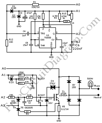
Soft Light Dimmer
This circuit is a soft light dimmer that utilizes the IGBT STGP10N50A and the TS555 timer as its primary components.
The soft light dimmer circuit is designed to control the brightness of incandescent lamps or other resistive loads by adjusting...
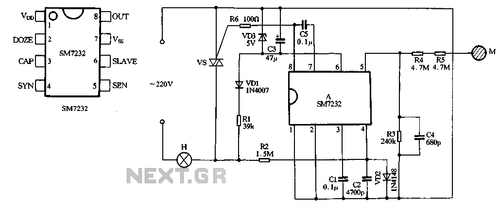
SM7232, CS7232 dimming control ASIC circuit
The core component of the circuit is the dimmer, utilizing the SM7232 integrated circuit. The pin configuration includes: 1) VDD, the positive power supply terminal; 2) DOZE; 3) CAP; 4) SYN, which synchronizes input power frequency using an internal PLL...

Halogen Lamp Dimmer With Soft Start
Most dimmers utilize pulse width modulation (PWM) to regulate the amount of power supplied to the lamp. Those that are packaged with a switch faceplate...
Dimmers that employ pulse width modulation (PWM) function by rapidly turning the power supplied to the...
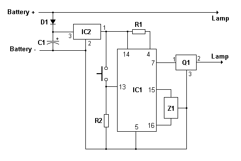
dimmer Controller circuit
Connect a 12-volt, 20-watt lamp and a 12-volt battery to the circuit, ensuring correct battery polarity. Momentarily pressing and releasing the button will turn the lamp on. Repeatedly pressing the button will cycle through different power levels. Pressing and holding...
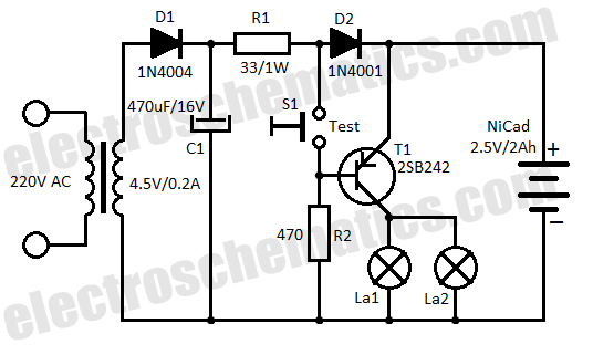
Automatic Lamp Dimmer Circuit
This automatic light dimmer circuit enables controlled lighting that gradually turns on or off. The operation is as follows: when switch S1 is closed, capacitor C1 charges slowly. Once the voltage across C1 reaches 0.6 volts, transistor T1 begins to...
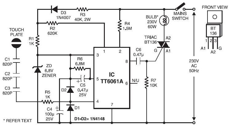
Light Dimmers Circuits
Typically, when a car door is closed, the dome light turns off immediately. This circuit allows the dome light to gradually fade in brightness before eventually turning off. An electronic transformer dims halogen lamps and is a straightforward device that...
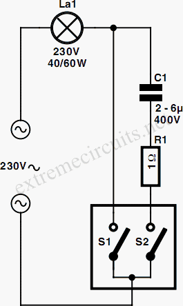
Two-Position Dimmer
This simple dimmer consists of only two components and can be easily integrated into a mains switch. It is essential to first switch off the associated branch circuit in the fuse box, as mains voltage poses a danger. The circuit...
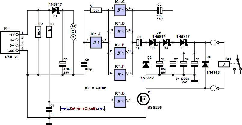
Computer Off Switch
How often does it happen that a user closes down Windows and then forgets to turn off the computer? This circuit addresses that issue by automatically powering off the computer after Windows has been shut down.
This circuit operates by monitoring...
HIGHWAY ALERT SIGNAL LAMP
The lighting system of a motor vehicle comprises lighting and signaling devices mounted or integrated at the front, sides, rear, and sometimes the top of the vehicle. This system's purpose is to provide illumination for the driver to operate the...