


Fluorescent lamp driver circuit composed of FET
#fluorescent lamp
#FET
#LC resonant circuit
#bidirectional breakdown diode
#starting circuit
#AC power
#resonant current
#gate threshold voltage
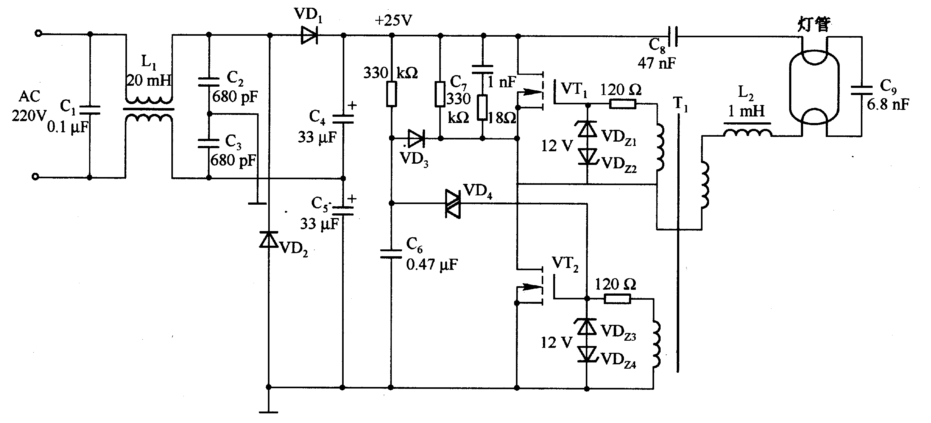
Description: A fluorescent tube is connected in an LC resonant circuit consisting of inductor L2 and capacitor C9. The bidirectional breakdown diode VD4 initiates the starting circuit. When AC power is applied, the gate potential of transistor VT2 increases due to VD4. Once the voltage surpasses the gate threshold voltage, VT2 becomes conductive. Consequently, the resonant current flows through capacitor C8, the fluorescent tube, resonant capacitor C9, choke L2, and the winding of drive transformer T1 powered by a +25 V DC voltage. The oscillation cycle is determined by C9, L2, and T1. Prior to the light turning on, the resonant state is established by components C9, L2, and transistors VT1 and VT2.
The described circuit operates as a starting mechanism for a fluorescent tube using an LC resonant configuration. The inductor (L2) and capacitor (C9) form the core of the resonant circuit, which is essential for generating the high-frequency oscillations required to ignite the fluorescent tube. The bidirectional breakdown diode (VD4) serves a crucial role in initiating the conduction of transistor (VT2) by allowing the gate voltage to rise when AC power is supplied.
When the AC voltage reaches a certain threshold, it triggers VT2, allowing current to flow through the circuit. This current travels through capacitor C8, which helps in stabilizing the voltage across the fluorescent tube, and subsequently through the fluorescent tube itself, which begins to emit light. The resonant behavior of the circuit is pivotal; it allows for efficient energy transfer and ensures that the voltage across the fluorescent tube is sufficient to sustain illumination.
The choke (L2) and the winding of the drive transformer (T1) are also integral to the circuit, as they assist in managing the current and voltage levels, ensuring that the system operates within safe parameters while providing the necessary energy for the fluorescent tube. The oscillation cycle, determined by the interplay of C9, L2, and T1, defines the frequency at which the circuit operates, influencing the performance and efficiency of the fluorescent lighting.
In summary, the interaction between the components—VD4, VT2, C8, C9, L2, and T1—creates a robust circuit that not only starts the fluorescent tube but also ensures its efficient operation through resonant behavior. This design exemplifies the application of LC circuits in lighting technology, highlighting the importance of each component in achieving the desired functionality.Fluorescent tube is connected in the LC resonant circuit composed of L2 and C9. Bidirectional breakdown diode VD4 is starting circuit. When AC power is connected, VT2 gate potential increases by VD4; when the voltage exceeds the gate threshold voltage, VT2 is conducted. Thus, the resonant current folws C8, fluorescent wire, resonant capacitor C9, choke L2, the winding of drive transformer Tl by +25 V DC voltage, and the oscillation cycle is decided by C9, L2, and T1. Before the light iturning on, the resonant state is decided by the C9, L2, and VT1, VT2.
The described circuit operates as a starting mechanism for a fluorescent tube using an LC resonant configuration. The inductor (L2) and capacitor (C9) form the core of the resonant circuit, which is essential for generating the high-frequency oscillations required to ignite the fluorescent tube. The bidirectional breakdown diode (VD4) serves a crucial role in initiating the conduction of transistor (VT2) by allowing the gate voltage to rise when AC power is supplied.
When the AC voltage reaches a certain threshold, it triggers VT2, allowing current to flow through the circuit. This current travels through capacitor C8, which helps in stabilizing the voltage across the fluorescent tube, and subsequently through the fluorescent tube itself, which begins to emit light. The resonant behavior of the circuit is pivotal; it allows for efficient energy transfer and ensures that the voltage across the fluorescent tube is sufficient to sustain illumination.
The choke (L2) and the winding of the drive transformer (T1) are also integral to the circuit, as they assist in managing the current and voltage levels, ensuring that the system operates within safe parameters while providing the necessary energy for the fluorescent tube. The oscillation cycle, determined by the interplay of C9, L2, and T1, defines the frequency at which the circuit operates, influencing the performance and efficiency of the fluorescent lighting.
In summary, the interaction between the components—VD4, VT2, C8, C9, L2, and T1—creates a robust circuit that not only starts the fluorescent tube but also ensures its efficient operation through resonant behavior. This design exemplifies the application of LC circuits in lighting technology, highlighting the importance of each component in achieving the desired functionality.Fluorescent tube is connected in the LC resonant circuit composed of L2 and C9. Bidirectional breakdown diode VD4 is starting circuit. When AC power is connected, VT2 gate potential increases by VD4; when the voltage exceeds the gate threshold voltage, VT2 is conducted. Thus, the resonant current folws C8, fluorescent wire, resonant capacitor C9, choke L2, the winding of drive transformer Tl by +25 V DC voltage, and the oscillation cycle is decided by C9, L2, and T1. Before the light iturning on, the resonant state is decided by the C9, L2, and VT1, VT2.
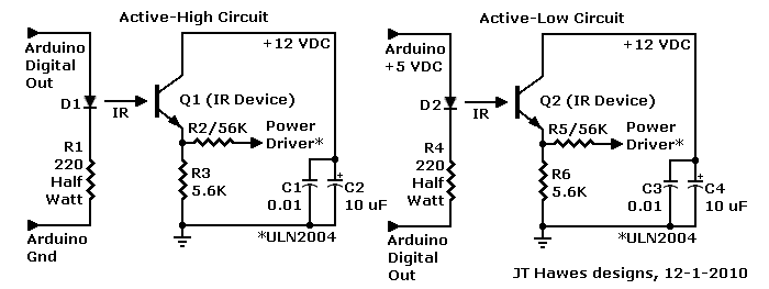
MPF102 FET Preamplifier Arduino
A Darlington transistor can enhance circuit performance, although it introduces slight complexity. The advantage of using a Darlington configuration lies in its capability to achieve low output impedance. The recommended component is the 2N6426 from Mouser, with alternatives such as...
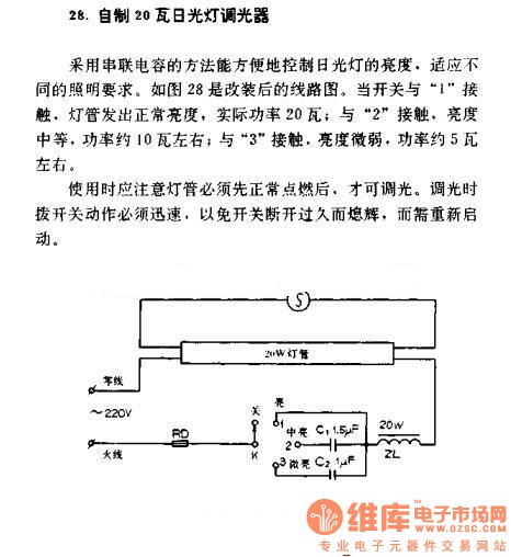
Homemade 20W fluorescent lamp dimmer circuit diagram
A homemade 20W fluorescent lamp dimmer utilizes a series capacitor connection to effectively control the brightness of fluorescent lamps, allowing for adaptability to various lighting requirements. In the modified circuit diagram (Figure 28), when the switch is set to position...
fet small signal analysis
A platform for sharing and discovering articles and documents. Users can upload their knowledge, share it with others, or search through the database to find relevant articles.
This platform serves as a collaborative space where individuals can contribute their expertise in...
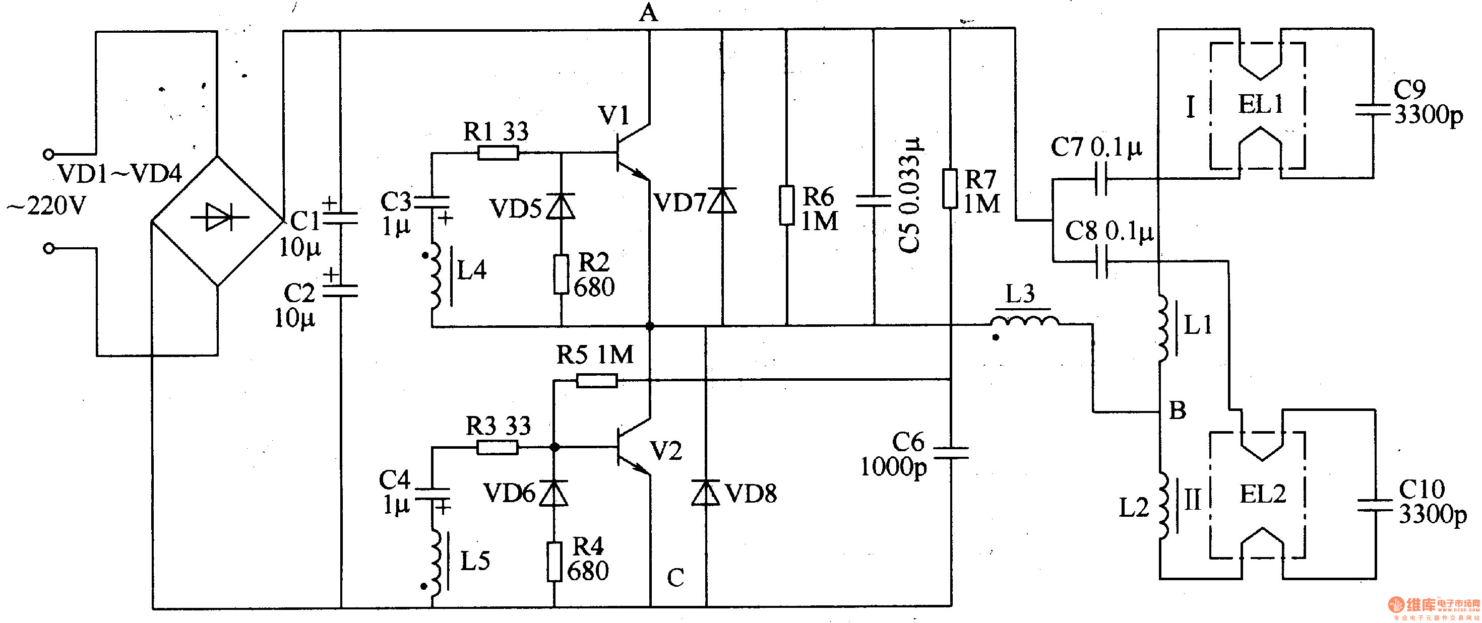
Fluorescent lamp electronic ballast
The electronic ballast circuit for fluorescent lamps comprises a rectifier filter circuit, a high-frequency oscillator circuit, and an output circuit, as illustrated in Figure 3-202. The rectifier filter circuit consists of rectifier diodes VD1-VD4 and filter capacitors C1 and C2....
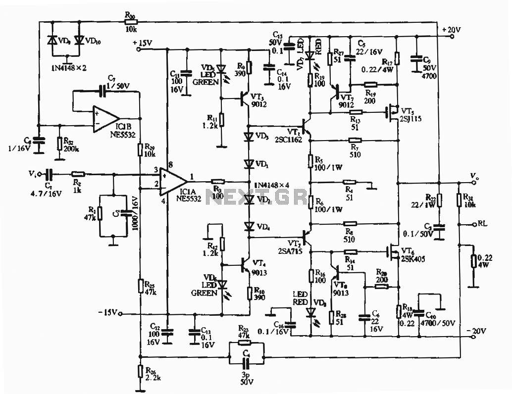
30W amplifier circuit
The circuit utilizes an FET amplifier configuration for output, incorporating an NE5532 operational amplifier powered by a 15V supply. The output stage features a FET that amplifies the voltage after passing through several stages. The bias circuit for the output...
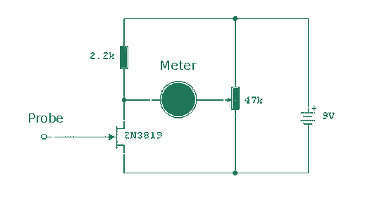
Static Electricity Detector
This circuit relies upon the extra high input impedance of a FET, and also demonstrates the gate terminals sensitivity to changes in voltage. The gate terminal here is left open circuit, connected only to the "probe" this being just a...
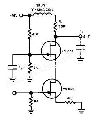
FET Cascode Video Amplifier
This circuit is a FET Cascode Video Amplifier. The cascode amplifier FET used for video applications has a very low input impedance and nearly zero feedback reduction. The 2N3823 transistor was selected due to its low capacitance and high transconductance...

FET applications
The Field Effect Transistor (FET) features a very high input impedance, approximately 100 Megaohms for Junction FETs (JFETs) and between 10^4 to 10^9 Megaohms for Metal-Oxide-Semiconductor FETs (MOSFETs). This characteristic effectively eliminates the major limitations of conventional transistors, which typically...

12VDC Fluorescent Lamp Driver
Several individuals have struggled to locate the transformer necessary for the Black Light project. Consequently, an investigation was conducted to identify a fluorescent lamp driver that does not necessitate any specialized components. A suitable option was discovered in Electronics Now....