


Game Show Indicator Lights (Whos First)
#game show
#indicator lights
#button press
#first responder
#LED
#timing circuit
#competitive
#multi-player
#fun
#electronics project

Description: Game Show Indicator Lights (Who's First) Circuit The circuit below activates a light corresponding to the first of several buttons pressed in a Who's First game. Three stages are shown, but the circuit can be extended to include additional stages.
The Game Show Indicator Lights circuit is designed to determine and visually indicate which contestant presses their button first in a competitive game setting. The basic configuration consists of multiple input buttons, each connected to a logic circuit that detects the first button pressed.
In the initial stage of the circuit, each button is linked to a resistor-capacitor (RC) network that helps debounce the button press, ensuring that only a clean signal is registered when a button is activated. The outputs from the buttons are fed into a priority encoder or a simple comparator circuit that assesses the signals and determines which button was pressed first.
Once the first button is identified, the logic circuitry activates a corresponding indicator light, which can be implemented using light-emitting diodes (LEDs) or incandescent bulbs. The indicator lights are connected through a transistor switch or a relay, allowing for higher power output to drive the lights without damaging the logic components.
For scalability, the circuit can be expanded to include additional buttons and corresponding indicator lights. This is achieved by cascading additional stages of logic or using multiplexing techniques to manage multiple inputs efficiently. The design can also incorporate features such as a reset button to clear the previous indication and prepare for the next round of play.
Overall, the Game Show Indicator Lights circuit combines logic design with visual output to create an engaging and interactive experience for participants, making it suitable for various game show formats and competitive events.Game Show Indicator Lights (Who`s First) Circuit The circuit below turns on a light corresponding to the first of several buttons pressed in a Who`s First game. Three stages are shown but the circuit can be extended to include a..
The Game Show Indicator Lights circuit is designed to determine and visually indicate which contestant presses their button first in a competitive game setting. The basic configuration consists of multiple input buttons, each connected to a logic circuit that detects the first button pressed.
In the initial stage of the circuit, each button is linked to a resistor-capacitor (RC) network that helps debounce the button press, ensuring that only a clean signal is registered when a button is activated. The outputs from the buttons are fed into a priority encoder or a simple comparator circuit that assesses the signals and determines which button was pressed first.
Once the first button is identified, the logic circuitry activates a corresponding indicator light, which can be implemented using light-emitting diodes (LEDs) or incandescent bulbs. The indicator lights are connected through a transistor switch or a relay, allowing for higher power output to drive the lights without damaging the logic components.
For scalability, the circuit can be expanded to include additional buttons and corresponding indicator lights. This is achieved by cascading additional stages of logic or using multiplexing techniques to manage multiple inputs efficiently. The design can also incorporate features such as a reset button to clear the previous indication and prepare for the next round of play.
Overall, the Game Show Indicator Lights circuit combines logic design with visual output to create an engaging and interactive experience for participants, making it suitable for various game show formats and competitive events.Game Show Indicator Lights (Who`s First) Circuit The circuit below turns on a light corresponding to the first of several buttons pressed in a Who`s First game. Three stages are shown but the circuit can be extended to include a..
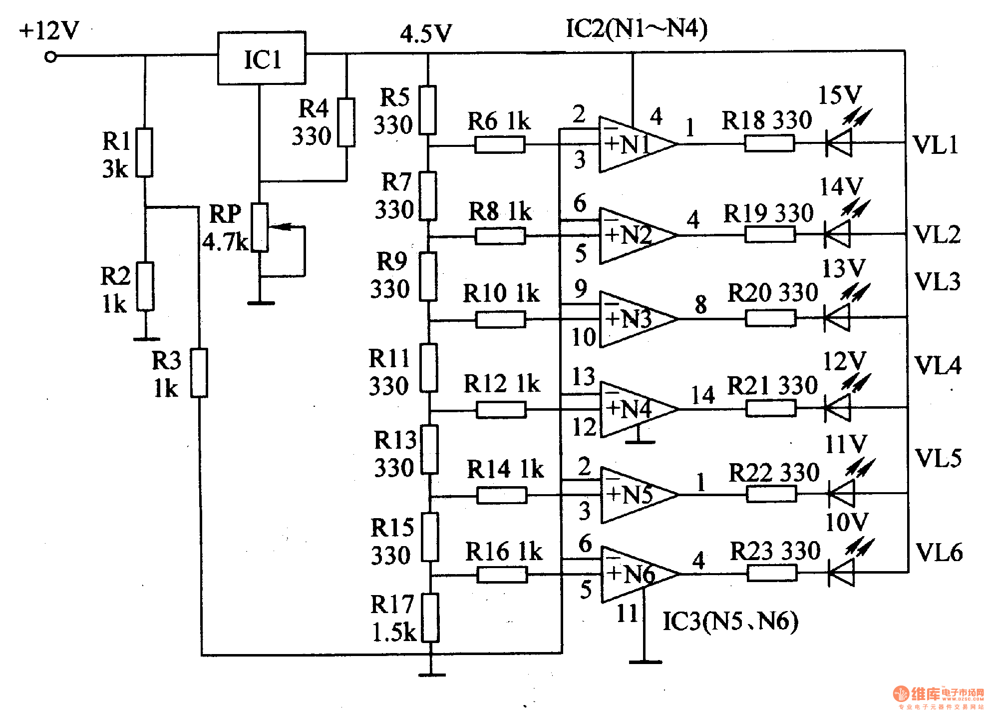
The LED car voltmeter (2)
This document introduces an LED car voltmeter constructed using the op-amp LM312 and LED components. It is designed to display six voltage levels ranging from 10V to 15V, with each level representing a 1V increment. The working principle of the...
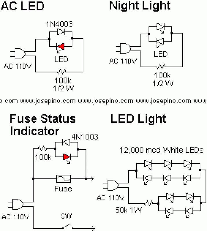
How to connect LED's directly to MAINS
A LED is defined as "light-emitting diode: diode such that light emitted at a p-n junction is proportional to the bias current; color depends on the material used." As the LED is a diode, it doesn't conduct electricity in both...

optical apd rx1
Many types of LEDs exhibit gain effects similar to those of an avalanche photodiode when reverse-biased. This phenomenon has been observed in the voltage range of 25-300 volts, with the voltage, spectral response, and overall sensitivity/gain varying based on the...
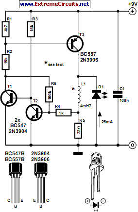
Thrifty LED Protector
An LED will fail if the current flowing through it is excessively high. This issue can be easily resolved by incorporating a simple resistor in series, which is an effective and low-cost solution. However, as the power supply voltage increases,...

sequential led bar graph circuit
The article explains a straightforward method for creating an incremental LED bar graph using the IC 4017, which has specifications that may not fully align with current requirements. It discusses how to modify the IC for these operations. The method...
dancing lights circuit diagram
This circuit serves as a decorative element or indicator, featuring adjustable flashing or dancing speeds of LEDs and the ability to create various light patterns. It consists of two astable multivibrators: one formed by transistors T1 and T2, and the...
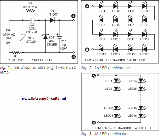
Ultra Bright LED Lamp circuit
This ultra-bright white LED lamp operates on 230V AC with low power consumption. It is suitable for illuminating VU meters, SWR meters, and similar applications. The ultra-bright LEDs available in the market range from Rs 8 to 15. These LEDs...
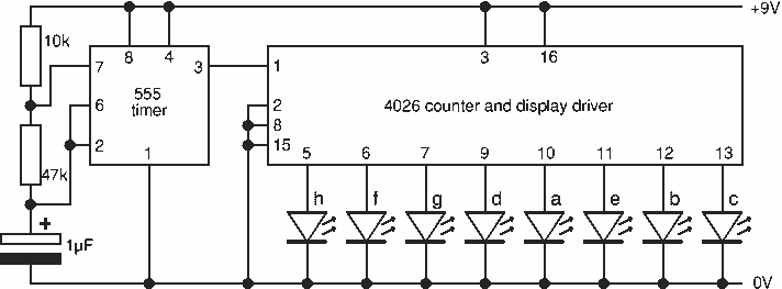
8 Random Flashing Leds Circuit
This project flashes eight LEDs in an apparently random manner. It uses a 4060 combined counter and display driver IC which is designed for driving 7-segment LED displays. The sequence is not really random because seven of the LEDs would...
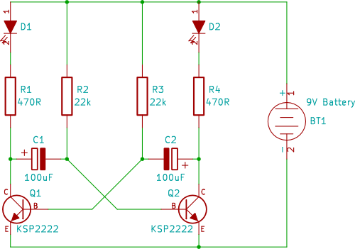
dual LED flasher
A two-transistor circuit that alternately flashes two LEDs on and off. This tutorial demonstrates how beginners in electronics can build this simple circuit on a breadboard.
This circuit utilizes two NPN transistors configured in a flip-flop arrangement, which allows for the...