


Homemade exposure unit
#exposure unit
#UV tubes
#ballasts
#wiring
#DIY
#epoxy circuit
#drilling
#wood mounting
#lighting setup
#homemade
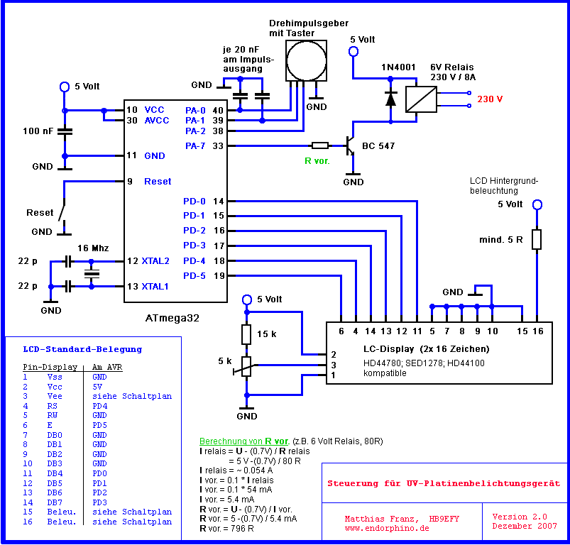
Description: Each tube socket has two plastic nibs on the back. For each socket, two holes were drilled into the circuit material. The socket nibs were then pressed into the drilled holes. Finally, a strip of epoxy circuit material was secured to a wood slat. The wiring diagram for driving one or two tubes is printed on the top of the magnetic ballasts. In this case, each magnetic ballast drives two tubes. Additionally, each tube requires its own fluorescent starter. The four starters in the upper right corner, along with the two vertically mounted magnetic ballasts, are connected to the four top UV tubes. The two single starters at the lower right, along with the horizontally mounted magnetic ballast, drive the two lower UV tubes. To connect all components, 0.75 mm² stranded cable was used, with the ends tinned. This was necessary because all components had clamp connectors without screws. To enhance the appearance of the wiring, hot glue was applied. The tubes take approximately two seconds to ignite. It is noted that one end of the tube appears slightly brighter than the other; however, since the board is intended to be placed in the middle, no quality issues are anticipated. The base plate will eventually be covered by a white mat cardboard to act as a reflector, while the side walls will remain painted black to minimize light scatter. The timing device is constructed using an Atmel ATmega32 microcontroller. Prototypes of the timer are shown using an Atmel evaluation board and a custom test board. The test board includes a 2x16 LCD display, a potentiometer for LCD contrast, a rotary encoder, ten LEDs, a potentiometer for A/D tests, and several push-buttons. All components can be connected via cable bridges to the microcontroller ports. The timer code was written in BASCOM AVR Basic and programmed using a serial device programmer called PonyProg. The LCD was connected to the ATmega32 as specified in the BASCOM AVR application notes. The rotary encoder includes a built-in push-button, but an external button can also be used to start the timer. A 6-volt relay is employed for the switching stage, with a flyback diode included to protect the transistor powering the relay. The series resistor for the transistor should be about 10% of the expected collector/emitter current. The rotary encoder allows the exposure time to be set in increments of five seconds. Pressing the button on the rotary encoder initiates the countdown, while the reset button can be used to stop or restart the countdown. The selected exposure time is stored in the EEPROM of the ATmega32. Upon resetting the counter or re-powering, the stored exposure time is retrieved from the internal EEPROM and used as the new start value, eliminating the need to manually record the exposure time. The timer code, written in BASCOM AVR Basic, includes extensive comments for clarity. Timer1 of the ATmega32 is utilized to generate a one-second cycle, providing sufficient accuracy for this application. The program occupies only 5% (~1 KB) of the available 32 KB on the ATmega32, allowing it to be programmed with the free version of the BASCOM AVR controller, which is limited to 4 KB. The decision to use an ATmega32 was based on its availability in the parts inventory.
The circuit design involves a series of interconnected components that facilitate the operation of UV tubes through a microcontroller-based timing system. Each tube socket is securely mounted to the circuit board, ensuring stable connections for the electrical components. The magnetic ballasts are strategically positioned to drive multiple tubes, with each ballast paired with its corresponding fluorescent starter to ensure proper ignition and operation of the tubes.
The wiring utilizes tinned stranded cables to ensure reliable connections to the clamp connectors, which are integral to the overall assembly. The application of hot glue not only enhances the aesthetic of the wiring but also provides additional strain relief for the connections, minimizing the risk of disconnections during operation.
The microcontroller serves as the central control unit, managing the timing functions and user inputs. The inclusion of an LCD display allows for real-time feedback and user interaction, while the rotary encoder provides an intuitive method for setting the exposure time. The design incorporates a relay for switching the load, which is essential for controlling the power to the UV tubes.
The use of a flyback diode is critical in protecting the microcontroller from voltage spikes generated by the relay, ensuring the longevity and reliability of the circuit. The EEPROM functionality allows for persistent storage of user settings, enhancing the user experience by retaining preferences across power cycles.
In summary, this circuit exemplifies a well-thought-out design that integrates various electronic components to achieve a functional and user-friendly system for controlling UV tube exposure with precise timing capabilities. The choice of components and the attention to detail in wiring and assembly contribute to a robust and efficient electronic device.Each tub sockets has 2 plastic nibs on the back. For each socket I drilled 2 holes into circuit material. Then I pressed the socket nibs into the drill holes. Finally I screwed the stripe of epoxy circuit material to the wood slat. The wiring diagram to drive 1 or 2 tubes is printed on the top of the magnetic ballasts (see picture no. 14). In my c ase every magnetic ballast is driving 2 tubes. In addition every tube needs of course its own fluorescent starter. The 4 starters in the right upper corner as well as the 2 vertically mounted magnetic ballasts are connected to the 4 top uv tubes. The 2 single starters at the right bottom as well as the horizontal mounted magnetic ballast driving the 2 lower uv tubes.
To wire all parts together I used 0. 75 mm ² strand cable which I tinned at the ends. This was required as all parts had these clamp connectors (without any screws). To make the wiring look a little bit nicer I used quite some hot glue. The tubes need approx 2 seconds to ignite. You can see on the photo that one end of the tube is actually a bit brighter than the other end. However - as the board is supposed to be placed in the middle I do not expect any quality problems. Picture 6 shows actually the same but the wood was painted in black now (a bit of isopropanol and few drops of refill ink for a black Edding ® pen, as this mixture is drying very fast. Don`t forget to open the window!) The base plate will later on be covered by a white mat carton (as a kind of reflector).
The side walls will stay painted in black to avoid potential light scatter. The timing device was made with a Atmel ® ATmega32 microcontroller. Picture 7 and 8 shows the prototype of the timer using an Atmel evaluation board from Pollin Elektronik ® (green board) and my own test board. My homemade test board contains a 2*16 LCD display, a pot for the LCD contrast, rotary encoder, 10 LEDs, a pot for A/D tests and several push-buttons.
All parts can be connected via cable bridges with all microcontroller ports. The code for the timer was written in BASCOM AVR ® Basic. The controller was programed with a serial device programmer called PonyProg ® (to use the Pollin evaluation with PonyProg please I used the following settings ). The LCD was connected to the ATmega exactly as discribed in the BASCOM AVR application notes. The rotary encode I use has a build in push-button but you can use an external one as well to start the timer.
For the switching stage a 6 volt relay was used. Don`t forget the fly back diode to protect the transistor powering the relay. The series resistor for the transistor stage should be about 10% of the expected collector/emitter current. With the rotary encoder the exposure time can be chosen in steps of 5 seconds. When pressing the button build into the rotary encoder the countdown starts. To stop or restart the countdown press the reset button. When pressing the start button the chosen exposure time will be stored in the eeprom of the ATmega. After resetting the counter or re-powering the value of the stored exposure time is read from the internal eeprom and used as new start value.
No need to write down or remind the exposure time - the counter stores the value for you. The code written in BASCOM AVR Basic can be found here. The code contains quite a lot of comments and is hopefully self-explanatory. To generate the 1 second cycle the timer1 of the ATmega32 was used. Time1 creates a reproducibly and for this purpose precise enough accuracy. If you are a high-precision fetishist feel free to program it in assembler. This program for the timer needs only 5% (~1kb) of the available 32kb of the used ATmega32. You can therefore program the microcontroller with the free version of the BASOM AVR controller (the free version is limited to 4kb). I finally used an ATmega32 because it was simply the first one I found in my spare part box. In case the program reacts like in slow
The circuit design involves a series of interconnected components that facilitate the operation of UV tubes through a microcontroller-based timing system. Each tube socket is securely mounted to the circuit board, ensuring stable connections for the electrical components. The magnetic ballasts are strategically positioned to drive multiple tubes, with each ballast paired with its corresponding fluorescent starter to ensure proper ignition and operation of the tubes.
The wiring utilizes tinned stranded cables to ensure reliable connections to the clamp connectors, which are integral to the overall assembly. The application of hot glue not only enhances the aesthetic of the wiring but also provides additional strain relief for the connections, minimizing the risk of disconnections during operation.
The microcontroller serves as the central control unit, managing the timing functions and user inputs. The inclusion of an LCD display allows for real-time feedback and user interaction, while the rotary encoder provides an intuitive method for setting the exposure time. The design incorporates a relay for switching the load, which is essential for controlling the power to the UV tubes.
The use of a flyback diode is critical in protecting the microcontroller from voltage spikes generated by the relay, ensuring the longevity and reliability of the circuit. The EEPROM functionality allows for persistent storage of user settings, enhancing the user experience by retaining preferences across power cycles.
In summary, this circuit exemplifies a well-thought-out design that integrates various electronic components to achieve a functional and user-friendly system for controlling UV tube exposure with precise timing capabilities. The choice of components and the attention to detail in wiring and assembly contribute to a robust and efficient electronic device.Each tub sockets has 2 plastic nibs on the back. For each socket I drilled 2 holes into circuit material. Then I pressed the socket nibs into the drill holes. Finally I screwed the stripe of epoxy circuit material to the wood slat. The wiring diagram to drive 1 or 2 tubes is printed on the top of the magnetic ballasts (see picture no. 14). In my c ase every magnetic ballast is driving 2 tubes. In addition every tube needs of course its own fluorescent starter. The 4 starters in the right upper corner as well as the 2 vertically mounted magnetic ballasts are connected to the 4 top uv tubes. The 2 single starters at the right bottom as well as the horizontal mounted magnetic ballast driving the 2 lower uv tubes.
To wire all parts together I used 0. 75 mm ² strand cable which I tinned at the ends. This was required as all parts had these clamp connectors (without any screws). To make the wiring look a little bit nicer I used quite some hot glue. The tubes need approx 2 seconds to ignite. You can see on the photo that one end of the tube is actually a bit brighter than the other end. However - as the board is supposed to be placed in the middle I do not expect any quality problems. Picture 6 shows actually the same but the wood was painted in black now (a bit of isopropanol and few drops of refill ink for a black Edding ® pen, as this mixture is drying very fast. Don`t forget to open the window!) The base plate will later on be covered by a white mat carton (as a kind of reflector).
The side walls will stay painted in black to avoid potential light scatter. The timing device was made with a Atmel ® ATmega32 microcontroller. Picture 7 and 8 shows the prototype of the timer using an Atmel evaluation board from Pollin Elektronik ® (green board) and my own test board. My homemade test board contains a 2*16 LCD display, a pot for the LCD contrast, rotary encoder, 10 LEDs, a pot for A/D tests and several push-buttons.
All parts can be connected via cable bridges with all microcontroller ports. The code for the timer was written in BASCOM AVR ® Basic. The controller was programed with a serial device programmer called PonyProg ® (to use the Pollin evaluation with PonyProg please I used the following settings ). The LCD was connected to the ATmega exactly as discribed in the BASCOM AVR application notes. The rotary encode I use has a build in push-button but you can use an external one as well to start the timer.
For the switching stage a 6 volt relay was used. Don`t forget the fly back diode to protect the transistor powering the relay. The series resistor for the transistor stage should be about 10% of the expected collector/emitter current. With the rotary encoder the exposure time can be chosen in steps of 5 seconds. When pressing the button build into the rotary encoder the countdown starts. To stop or restart the countdown press the reset button. When pressing the start button the chosen exposure time will be stored in the eeprom of the ATmega. After resetting the counter or re-powering the value of the stored exposure time is read from the internal eeprom and used as new start value.
No need to write down or remind the exposure time - the counter stores the value for you. The code written in BASCOM AVR Basic can be found here. The code contains quite a lot of comments and is hopefully self-explanatory. To generate the 1 second cycle the timer1 of the ATmega32 was used. Time1 creates a reproducibly and for this purpose precise enough accuracy. If you are a high-precision fetishist feel free to program it in assembler. This program for the timer needs only 5% (~1kb) of the available 32kb of the used ATmega32. You can therefore program the microcontroller with the free version of the BASOM AVR controller (the free version is limited to 4kb). I finally used an ATmega32 because it was simply the first one I found in my spare part box. In case the program reacts like in slow
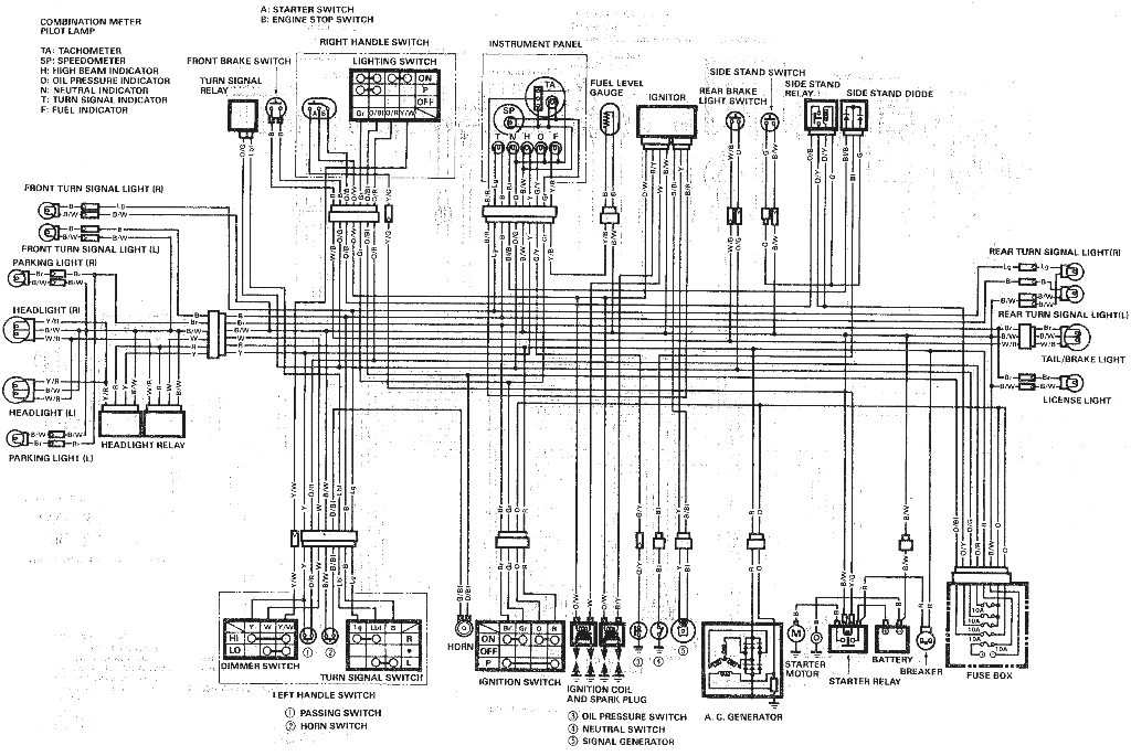
Suzuki Wiring Diagrams
Do not forget to seal your wire splices with heat shrink tubing. It provides tensile strength to wires, is flame-retardant, and protects against fraying. Heat shrink tubing forms a protective, insulated, water-resistant covering over wiring splices, crimp terminals, and solder...
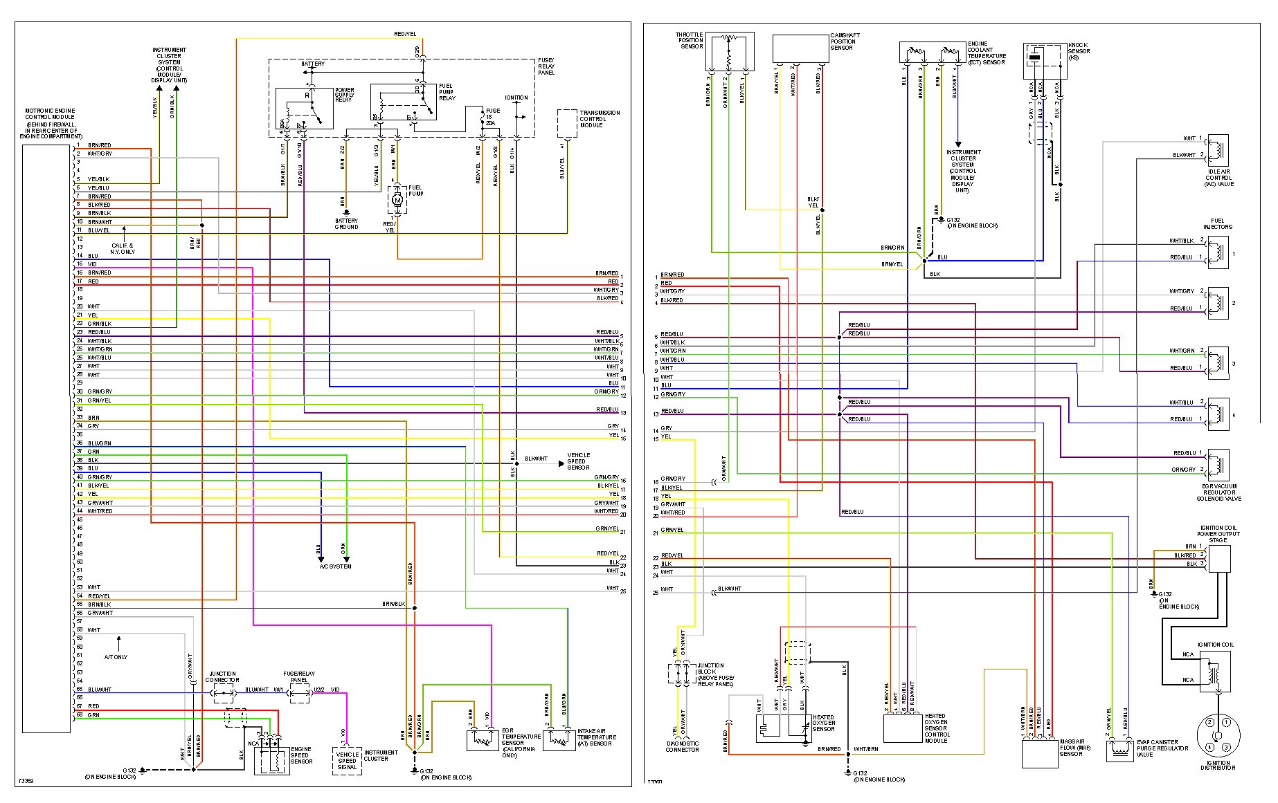
1994 Golf GTI wiring
I have purchased and sold 10 MK3 Jettas and 1 MK3 Golf. This is my first time posting on a forum. I paid $400 for a 1994 GTI with the intention of fixing it and reselling it. The car was...
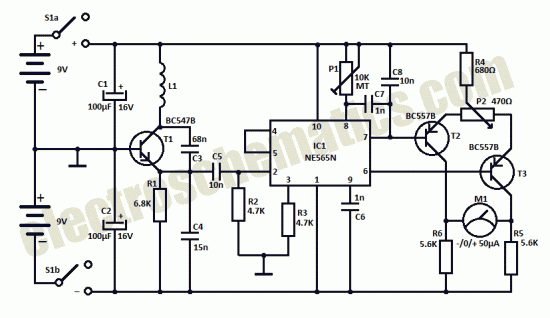
Homemade metal detector
This homemade metal detector circuit is designed to locate objects made of materials with relatively high magnetic permeability. While it may not be sensitive enough for detecting buried coins, it can effectively identify larger metallic treasures. The circuit operates using...
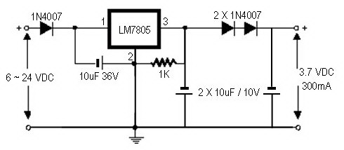
how to convert a 9v battery to 3.7v
A regulator circuit is needed for this DIY project. Familiarity with electronic components, circuitry, the use of a multitester, and a soldering iron is essential. The schematic diagram provided can accept an input voltage ranging from 6 to 24 volts...
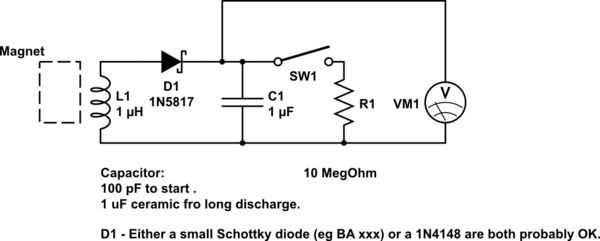
DIY kinetic energy harvester
A DIY kinetic energy harvester utilizing the electromagnetic method to generate electricity. The materials that will be used are currently known.
The project involves creating a kinetic energy harvester that converts mechanical energy from motion into electrical energy through electromagnetic induction....
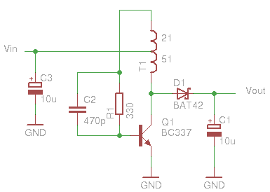
Glue stck torch
This project, developed around 2005, involves constructing a torch using a glue stick, which conveniently accommodates an AA battery within its plastic casing. To create a functional battery holder, contacts for both the positive and negative connections are necessary. The...
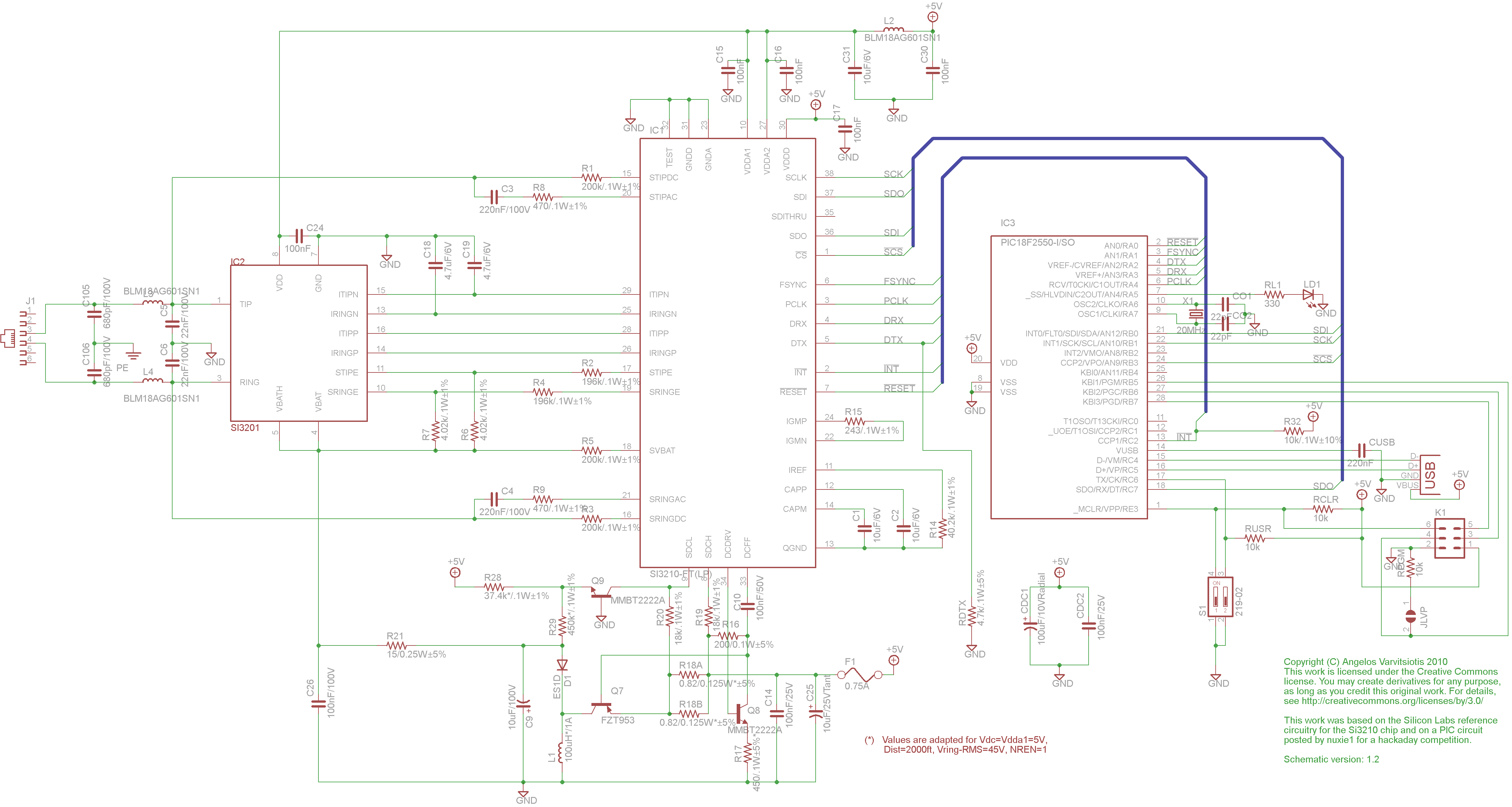
dyi setup and debugging guide
This page discusses the differences between assembled Open USB FXS dongle boards and DIY boards. While the assembled boards are fully tested and quality control approved, DIY boards may encounter various issues during assembly. Fortunately, most of these issues can...
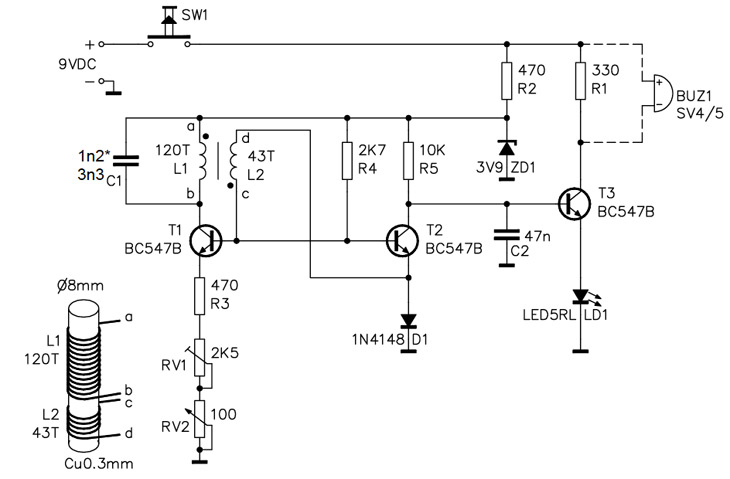
Homemade Metal Detector Kit
A simple home project can quickly become problematic if it encounters electric cables, gas, or water pipes, or the central heating system. Using a metal detector allows one to check for metal objects within walls, ceilings, or floors beforehand. An...
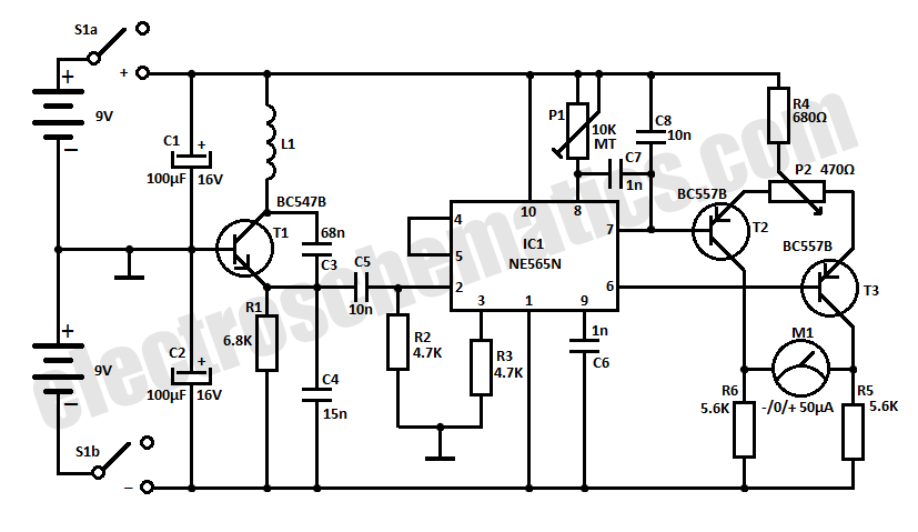
Homemade metal detector circuit
This homemade metal detector circuit will assist in locating objects made of materials with relatively high magnetic permeability. It is not suitable for detecting certain metals.
This metal detector circuit operates on the principle of electromagnetic induction, utilizing a coil of...