


infra red ir led flood light circuit
#IR LED
#voltage doubler
#555 timer
#pulse modulation
#battery-powered
#flood light
#4049 IC
#infrared
#PP3 battery
#low voltage
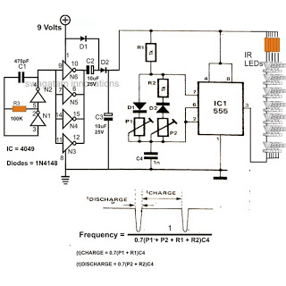
Description: The 4049 section serves as a fundamental voltage doubler circuit, enhancing a 9 V supply to approximately 15 V. This elevated voltage subsequently acts as the supply voltage for the following 555 pulse modulator section. A key characteristic of this infrared (IR) LED floodlight circuit is its ability to operate using only a single PP3 9-volt battery while delivering impressive infrared light output.
The 4049 voltage doubler circuit operates by utilizing the principles of capacitive charge and discharge, where two capacitors and diodes are arranged to effectively double the input voltage. The circuit typically consists of two diodes and two capacitors. During the first half of the AC cycle, one capacitor charges through the first diode, while the second capacitor charges through the second diode during the opposite half cycle. This configuration allows the output voltage to reach approximately double the input voltage, thus converting the 9 V from the PP3 battery to around 15 V.
This boosted voltage is crucial for the operation of the 555 pulse modulator, which is commonly used in various applications such as timers, pulse generation, and oscillators. The 555 timer can be configured in monostable or astable modes, allowing for versatile control over the LED operation. In this circuit, the 555 timer is likely configured to produce a square wave signal that drives the IR LEDs. The modulation of the LED output can be adjusted by changing the resistor and capacitor values connected to the 555 timer, enabling variations in pulse width and frequency.
The use of a single PP3 9-volt battery is advantageous for this circuit, as it provides a compact and portable power source. Despite its small size, the circuit is designed to maximize the efficiency of the IR LEDs, which are known for their high light output relative to power consumption. The combination of the voltage doubler and the 555 pulse modulator allows the circuit to achieve impressive infrared illumination levels, making it suitable for applications such as remote controls, night vision devices, and security lighting systems.
Overall, this circuit exemplifies an efficient design that leverages basic electronic components to achieve high performance while maintaining simplicity and portability.The 4049 section is the basic voltage doubler circuit which effectively boosts the 9 V supply to a level of around 15 V which further becomes the supply voltage for the next 555 pulse modulator section. The main feature of this infrared IR LED flood light circuit is that it utilizes just a single PP3 9 volt battery and yet is able to provide l
ights (IR) at dazzling levels.
The 4049 voltage doubler circuit operates by utilizing the principles of capacitive charge and discharge, where two capacitors and diodes are arranged to effectively double the input voltage. The circuit typically consists of two diodes and two capacitors. During the first half of the AC cycle, one capacitor charges through the first diode, while the second capacitor charges through the second diode during the opposite half cycle. This configuration allows the output voltage to reach approximately double the input voltage, thus converting the 9 V from the PP3 battery to around 15 V.
This boosted voltage is crucial for the operation of the 555 pulse modulator, which is commonly used in various applications such as timers, pulse generation, and oscillators. The 555 timer can be configured in monostable or astable modes, allowing for versatile control over the LED operation. In this circuit, the 555 timer is likely configured to produce a square wave signal that drives the IR LEDs. The modulation of the LED output can be adjusted by changing the resistor and capacitor values connected to the 555 timer, enabling variations in pulse width and frequency.
The use of a single PP3 9-volt battery is advantageous for this circuit, as it provides a compact and portable power source. Despite its small size, the circuit is designed to maximize the efficiency of the IR LEDs, which are known for their high light output relative to power consumption. The combination of the voltage doubler and the 555 pulse modulator allows the circuit to achieve impressive infrared illumination levels, making it suitable for applications such as remote controls, night vision devices, and security lighting systems.
Overall, this circuit exemplifies an efficient design that leverages basic electronic components to achieve high performance while maintaining simplicity and portability.The 4049 section is the basic voltage doubler circuit which effectively boosts the 9 V supply to a level of around 15 V which further becomes the supply voltage for the next 555 pulse modulator section. The main feature of this infrared IR LED flood light circuit is that it utilizes just a single PP3 9 volt battery and yet is able to provide l
ights (IR) at dazzling levels.
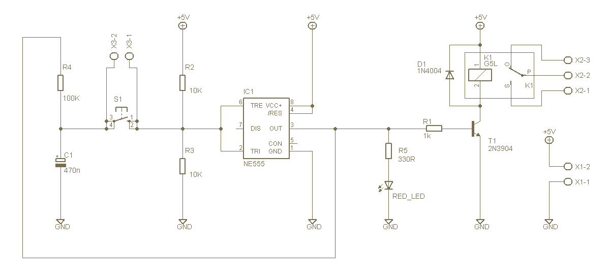
1 button ON / OFF Switch with 555
This project describes how to build a "soft touch" switch. By "soft touch" we mean that you have to push once to set device ON and push again to set device OFF. This kind of switch works by latching a...
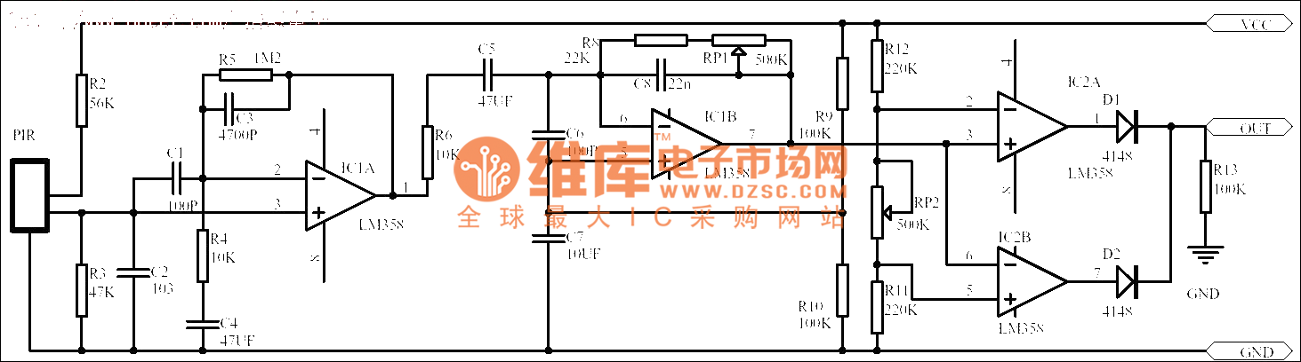
The passive human body infrared sensor circuit
Passive human body infrared sensor circuits are generally similar in design, although some may have fewer stages. The circuit illustrated is sourced from the NICERA manufacturer and is considered a classic example. The front-end stage consists of a low-frequency signal...
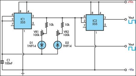
Variable on-off times circuit using two 555 timers
This timer utilizes two 555 integrated circuits (ICs) to adjust the desired output. The variable resistors VR1 and VR2 serve as potentiometers to modify the cycle speed. The circuit can be powered with a 9 to 12-volt power supply, consuming...

Camera Switcher
This circuit allows multiple cameras to be connected to a single monitor. It can be operated either manually or automatically. In automatic mode, a switch is connected to the output of a 555 astable multivibrator, which generates a continuous square...

Holiday Light Sequencer Circuit
The integrated circuit U1 (a 555 oscillator/timer) is configured as a conventional pulse generator. The frequency of the pulse generator is adjusted using potentiometer R11. Resistor R2 limits the maximum frequency attainable. The output from the pulse generator is connected...
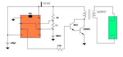
simple fluorescent inverter project
Fluorescent tubes contain mercury, which poses health risks. Improper disposal of these tubes is harmful to both the environment and health; therefore, recycling is a beneficial option. The 555 timer IC is utilized to generate a square wave voltage of...

Device that it is self-running
If the input is coming from a function generator's typical output clip leads, then the "black" lead or "-" or "ground" is connected to the circuit's ground. The ground of Pin 3 of a 555 timer must also be common...
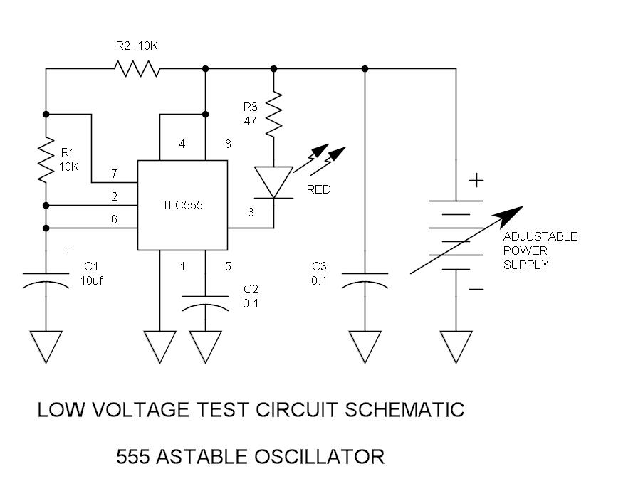
555 Low Voltage Operation
There have been stories regarding the suboptimal performance of the 555 timer IC when operated below a supply voltage (Vcc) of 5V, prompting an investigation into potential improvements for its operation.
The 555 timer IC is a versatile device commonly used...
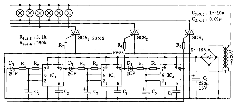
555 flow-control circuit diagram of a lantern
The circuit utilizes a 555 timer as its core component to control three lights through a cyclic trigger monostable delay circuit. The brightest light is controlled by a silicon-controlled rectifier (SCR) that determines the cycle of illumination. When pin 3...