


Lamp-flasher
#lamp-flasher
#power FETs
#astable multivibrator
#flash rate
#RC circuit
#switching
#LED
#timer
#oscillator
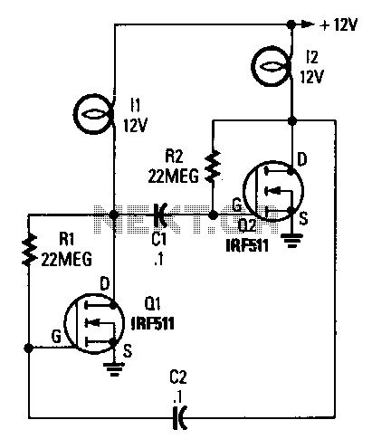
Description: The circuit consists of two power FETs configured as a simple astable multivibrator to alternately switch two lamps on and off. The resistor-capacitor (RC) values set the flash rate to approximately 1/3 Hz. By varying either the resistor or capacitor values, nearly any flash rate can be achieved. Increasing either C1 and C2 or R1 and R2 will slow the flash rate, while decreasing them will increase the rate.
The described circuit utilizes two power Field Effect Transistors (FETs) to create an astable multivibrator configuration, which is essential for generating a square wave output. This output is used to drive two lamps, allowing them to turn on and off alternately. The frequency of the flashing effect is determined by the timing components, specifically the resistors (R1, R2) and capacitors (C1, C2) connected in the circuit.
In an astable multivibrator, the two FETs are arranged in a feedback loop that continuously switches states. When one FET turns on, it allows current to flow through one lamp, while the other FET turns off, preventing current through the second lamp. This alternating action creates a visual effect of flashing lights. The rate of this flashing can be finely tuned by adjusting the RC values.
The relationship between the RC values and the flash rate is inversely proportional; as the capacitance or resistance increases, the time constant of the circuit rises, resulting in a slower flash rate. Conversely, reducing the values of C1, C2, R1, or R2 will decrease the time constant, leading to a quicker flashing effect.
In practical applications, selecting the right values for the resistors and capacitors allows for a wide range of flashing frequencies, making this circuit versatile for various lighting applications. The design can be implemented on a PCB or a breadboard for prototyping, ensuring that proper heat dissipation for the power FETs is considered to maintain reliability during operation.The circuit is built around two power FETs, which are configured as a simple astable multivibrator to alternately switch the two lamps on and off. The rc values given sets the flash rate to about 1/3 Hz. By varying either the resistor or capacitor values, almost any flash rate can be obtained. Increase either Cl and C2, or Rl and R2, and the flash rate slows. Decrease them and the rate increases.
The described circuit utilizes two power Field Effect Transistors (FETs) to create an astable multivibrator configuration, which is essential for generating a square wave output. This output is used to drive two lamps, allowing them to turn on and off alternately. The frequency of the flashing effect is determined by the timing components, specifically the resistors (R1, R2) and capacitors (C1, C2) connected in the circuit.
In an astable multivibrator, the two FETs are arranged in a feedback loop that continuously switches states. When one FET turns on, it allows current to flow through one lamp, while the other FET turns off, preventing current through the second lamp. This alternating action creates a visual effect of flashing lights. The rate of this flashing can be finely tuned by adjusting the RC values.
The relationship between the RC values and the flash rate is inversely proportional; as the capacitance or resistance increases, the time constant of the circuit rises, resulting in a slower flash rate. Conversely, reducing the values of C1, C2, R1, or R2 will decrease the time constant, leading to a quicker flashing effect.
In practical applications, selecting the right values for the resistors and capacitors allows for a wide range of flashing frequencies, making this circuit versatile for various lighting applications. The design can be implemented on a PCB or a breadboard for prototyping, ensuring that proper heat dissipation for the power FETs is considered to maintain reliability during operation.The circuit is built around two power FETs, which are configured as a simple astable multivibrator to alternately switch the two lamps on and off. The rc values given sets the flash rate to about 1/3 Hz. By varying either the resistor or capacitor values, almost any flash rate can be obtained. Increase either Cl and C2, or Rl and R2, and the flash rate slows. Decrease them and the rate increases.
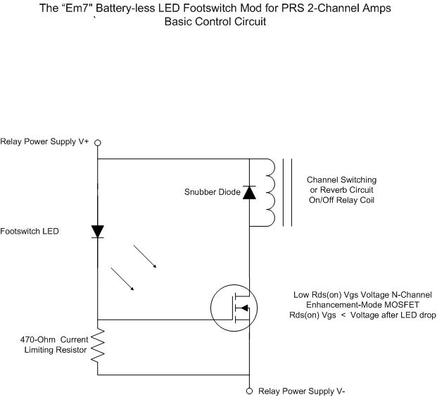
Battery less LED Footswitch Mod for the 2 Channels
For individuals seeking LED-based footswitching without the inconvenience of battery installation, a battery-less LED-based footswitch modification is being developed for 2-channel amplifiers. This solution is designed to work with the existing TRS jack and footswitch, and it will involve a...

Cheap led christmas light flasher circuit is controlled by audio
Individuals seeking a distinctive gift for Christmas and New Year may find this project appealing. Certification of this project will undoubtedly create a preference for it.
The project in question appears to be a creative endeavor aimed at providing a unique...
Nite Rider LED Lights
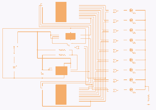
IC4, C1, R1 and R2 are used for the clock pulse which is fed to both the counters IC2 and IC3 Pin 14. IC1 is a Flip Flop and is used as a switch to enable either IC2 or IC3...
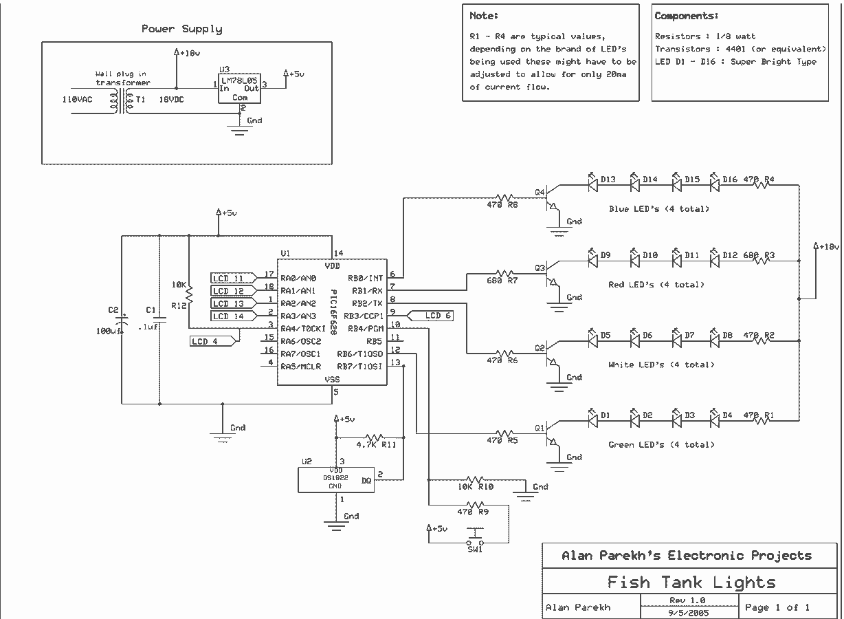
Fish Tank Lights and Temperature Detector
When the tank is cleaned the fish are removed and placed in a small amount of the tank water. The problem is that fish don’t like rapid temperature fluctuations. A simple in-tank or stick-on thermometer would have sufficed, but adding...
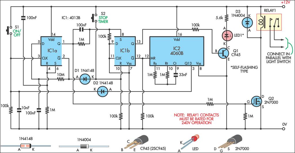
Switch Timer For Bathroom Light
This 9-minute timer switch can be utilized to control lighting in a toilet or bathroom. The timer is activated by pressing switch S1 and deactivated by pressing S1 again. If the timer is not manually turned off, the light will...
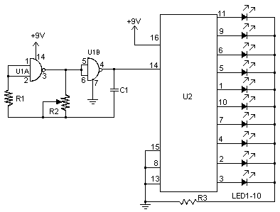
LED Chaser
I don't know why, but people like blinking lights. You see LED chasers everywhere, in TV shows (Knight Rider), movies, and store windows. This schematic is my version of a simple 10 LED chaser. There is no 555 timer used...

High-intensity LED Warning Flasher
This circuit was designed as a warning flasher to alert road users to dangerous situations in the dark. Alternatively, it can act as a bicycle light.
The circuit operates by utilizing a light-emitting diode (LED) as the primary visual alerting component....
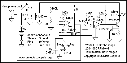
White LED Stroboscope
Finally, white LEDs are bright enough to use in a practical stroboscope. This circuit can operate as a bench-top stroboscope that, in conjunction with an oscilloscope or frequency meter and bench-top power supply, can accurately measure rotational speeds, or it...
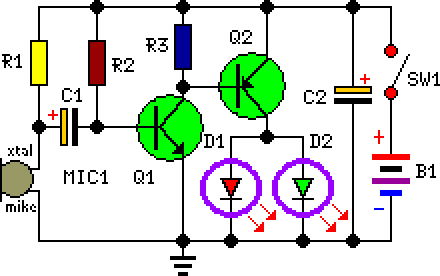
Flashing Eyes
This circuit is designed as a humorous Halloween gadget. It is intended to be placed at the back of a badge or pin featuring a typical Halloween character image, such as a pumpkin, skull, black cat, witch, or ghost. Two...