


LC189 making decorative lanterns with fans
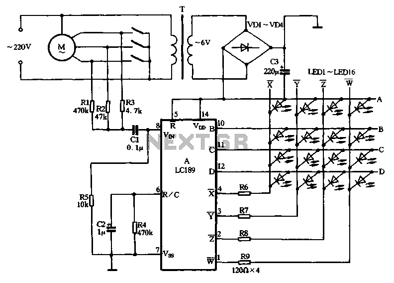
Description: The decorative light circuit for fans, as illustrated in Figure 2-130, consists of a step-down rectifier circuit, a lattice-specific integrated sound and light control module, and other components. The core device in this circuit is the LC189. This decorative lamp utilizes varying voltage amplitudes across the inductor to control fan speed, which in turn allows the LC189 to modulate the flash frequency of different LEDs. Higher voltage results in faster flashing, while lower voltage causes slower flashing. Resistors R1 to R3 are connected to a three-position fan speed control switch, while capacitor C1 is coupled to pin 8 of the LC189. Resistors R4 and C2 form an oscillation RC circuit for the external contact. The output waveform frequency changes with the amplitude of the input signal, and the outputs at terminals A to D connect to a 4x4 dot matrix. The light-emitting diodes (LED1 to LED16) are connected to the row and column lines, producing stunning visual effects as shown in Figure 2-127. Resistors R6 to R9 serve as current-limiting resistors for the arc tube, which should be adjusted based on the power supply voltage. For a 6V DC power supply, a resistance of 120 ohms is appropriate, while for a 12V supply, the current-limiting resistor should be increased to 390 ohms.
The decorative light circuit for fans operates by integrating various electronic components to achieve a visually appealing lighting effect synchronized with fan speed. The step-down rectifier circuit converts the AC input voltage to a lower DC voltage suitable for the operation of the LC189. This integrated circuit is essential for controlling the timing and intensity of the LEDs based on the voltage applied to the inductor, which directly influences the fan's operational speed.
The fan speed control switch, utilizing resistors R1 to R3, allows for user selection of three different speed settings. Each setting modifies the input voltage to the LC189, thereby altering the flashing frequency of the LEDs. Capacitor C1 plays a crucial role in stabilizing the voltage at pin 8 of the LC189, ensuring reliable performance.
The oscillation circuit formed by R4 and C2 is responsible for generating the necessary timing signals that drive the LED patterns. The varying amplitude of the input signal directly affects the output waveform frequency, which is critical for achieving the desired lighting effects. The outputs A to D connect to a 4x4 dot matrix configuration, where each LED is strategically placed to create dynamic visual displays.
The current-limiting resistors R6 to R9 are designed to protect the LEDs and the arc tube from excessive current, which could lead to damage. The choice of resistance values is dependent on the power supply voltage; thus, it is vital to select the appropriate resistor values to ensure the longevity and functionality of the circuit. This careful design consideration allows for a versatile and visually captivating decorative light circuit that enhances the ambiance of any space.Fans decorative light circuit in Figure 2-130, the circuit consists of step-down rectifier circuit, lattice specific integrated sound and light control roads and other componen ts. Core device circuit is LC189. This decorative lamp is the use of different voltage amplitude on the inductor fan speed, forcing LC189 control different LED flash frequency, voltage, high frequency fast flash, slow and vice versa. Resistance Rl ~ R3 connected on three-block fan speed control switch, the capacitor C1 is coupled to the input of LCI89 8 feet.
R4 and C2 are manifold outer contact oscillation RC components. Circuit output waveform frequency because the amplitude of the input signal varies, the output of A ~ D row and column output terminal f ~ r connected to 4x4 dot matrix, between the light emitting diode LED1 ~ 16 connected row line and column line, arc tube to press on section Figure 2-127 shows the level change and shiny, which can be formed is wonderful visual effects. Resistor R6 ~ R9 current limiting resistor of the arc tube, which along with the power supply voltage level may be, the machine uses 6V DC power supply, it is appropriate resistance 120 Q, if the power supply voltage of 12V, current limiting resistor should be increased to 390Q.
The decorative light circuit for fans operates by integrating various electronic components to achieve a visually appealing lighting effect synchronized with fan speed. The step-down rectifier circuit converts the AC input voltage to a lower DC voltage suitable for the operation of the LC189. This integrated circuit is essential for controlling the timing and intensity of the LEDs based on the voltage applied to the inductor, which directly influences the fan's operational speed.
The fan speed control switch, utilizing resistors R1 to R3, allows for user selection of three different speed settings. Each setting modifies the input voltage to the LC189, thereby altering the flashing frequency of the LEDs. Capacitor C1 plays a crucial role in stabilizing the voltage at pin 8 of the LC189, ensuring reliable performance.
The oscillation circuit formed by R4 and C2 is responsible for generating the necessary timing signals that drive the LED patterns. The varying amplitude of the input signal directly affects the output waveform frequency, which is critical for achieving the desired lighting effects. The outputs A to D connect to a 4x4 dot matrix configuration, where each LED is strategically placed to create dynamic visual displays.
The current-limiting resistors R6 to R9 are designed to protect the LEDs and the arc tube from excessive current, which could lead to damage. The choice of resistance values is dependent on the power supply voltage; thus, it is vital to select the appropriate resistor values to ensure the longevity and functionality of the circuit. This careful design consideration allows for a versatile and visually captivating decorative light circuit that enhances the ambiance of any space.Fans decorative light circuit in Figure 2-130, the circuit consists of step-down rectifier circuit, lattice specific integrated sound and light control roads and other componen ts. Core device circuit is LC189. This decorative lamp is the use of different voltage amplitude on the inductor fan speed, forcing LC189 control different LED flash frequency, voltage, high frequency fast flash, slow and vice versa. Resistance Rl ~ R3 connected on three-block fan speed control switch, the capacitor C1 is coupled to the input of LCI89 8 feet.
R4 and C2 are manifold outer contact oscillation RC components. Circuit output waveform frequency because the amplitude of the input signal varies, the output of A ~ D row and column output terminal f ~ r connected to 4x4 dot matrix, between the light emitting diode LED1 ~ 16 connected row line and column line, arc tube to press on section Figure 2-127 shows the level change and shiny, which can be formed is wonderful visual effects. Resistor R6 ~ R9 current limiting resistor of the arc tube, which along with the power supply voltage level may be, the machine uses 6V DC power supply, it is appropriate resistance 120 Q, if the power supply voltage of 12V, current limiting resistor should be increased to 390Q.
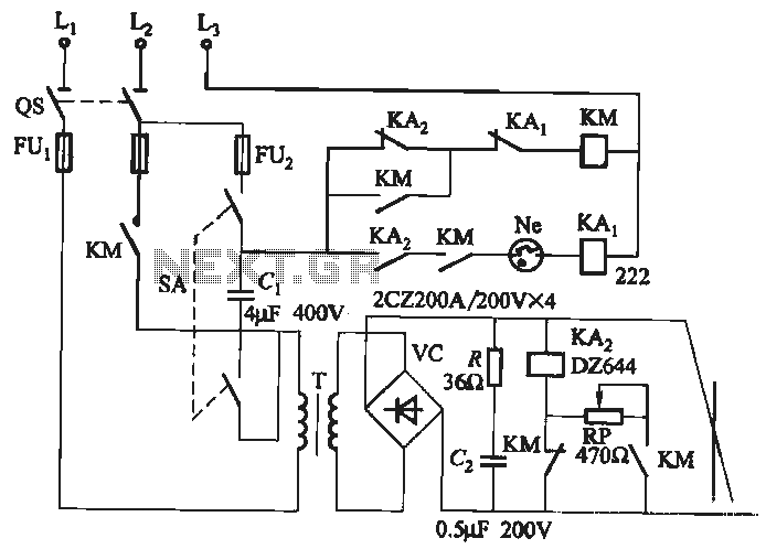
Single-phase rectifier DC welding power load from road circuit
A single-phase rectifier DC welding power load from the road circuit is presented. The contactor KM utilizes a CJ20-40A model rated for 220V. An adjustment potentiometer RP is employed to ensure proper arcing, while the relay KA2 is designed for...
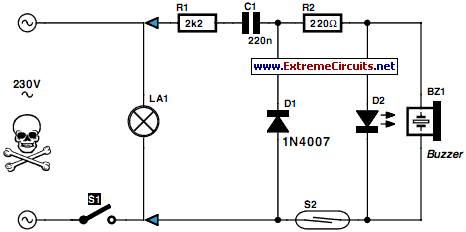
Put That Light Out
If the light in a seldom-used room, such as a loft, is forgotten and left on, it can remain illuminated for extended periods, leading to significant electricity costs. To address this issue, electronics enthusiasts can design a simple circuit to...
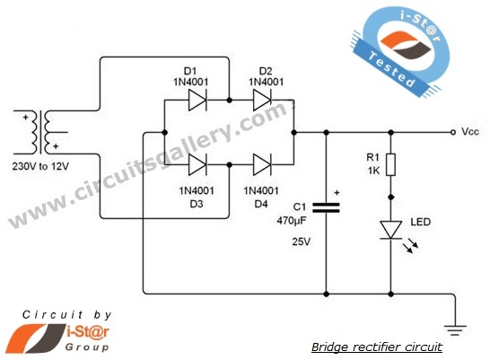
diode bridge rectifier circuits
A rectifier is an electronic circuit that converts AC voltage to DC voltage. It can be implemented using a combination of capacitors and diodes. The unique property of diodes, which allows current to flow in a single direction, is utilized...
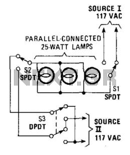
3-Way Light Control
This hookup is useful in certain house wiring situations where only two wires are available between switches, rather than the usual three-way setup that requires three wires. SI and S2 are standard three-way switches, while S3, a double-pole double-throw (DPDT)...
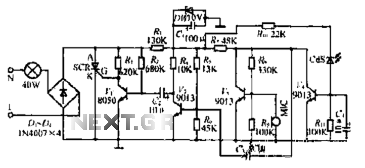
A sound and light control switch circuit
120V galvanic acupuncture salmon RI. The system features a wind-down rectification and a limit irrigation mechanism to achieve an amplitude of 24V. It includes isolation diodes and a steady stream over the circuit. The design ensures that a voltage of...
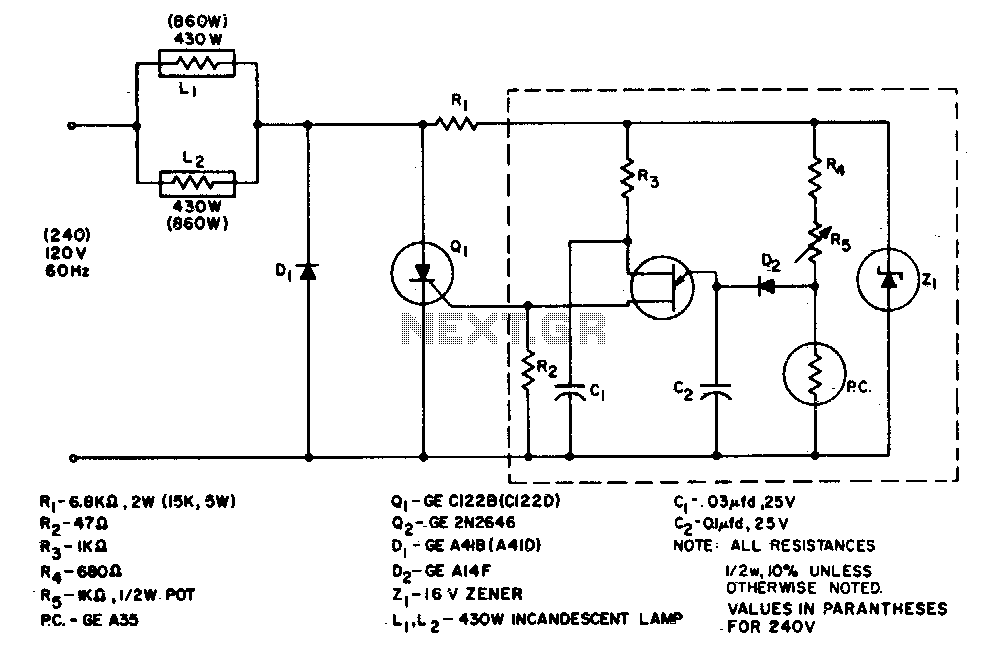
860 Watt limited-range light control
The system is designed to regulate an 860-watt lamp load from half to full power. This is achieved through the controlled half-plus-fixed half-wave phase control method. Applying half power to an incandescent lamp results in 30% of the full light...
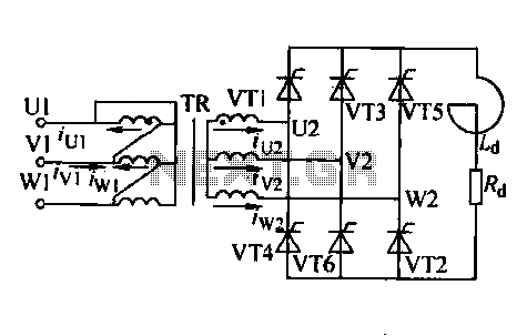
Three-phase controlled rectifier circuit
Trigger circuit routing forms include various types such as simple trigger circuits, single-junction transistor trigger circuits, synchronous sine wave trigger circuits, sawtooth transition phase shift (synchronous) trigger circuits, and integrated trigger circuits. This section presents individual cases for introduction due...
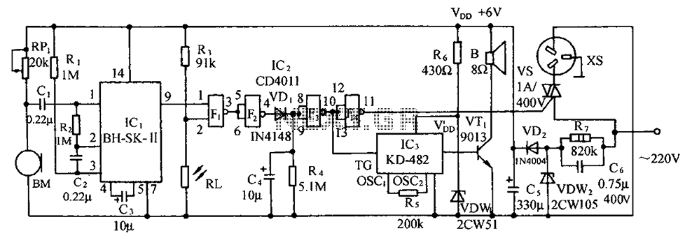
Sound and light double control switch socket electrical circuit diagram
The circuit illustrated includes a sound transducer sensing switch, an electrical light control switch, an SCR control circuit, a vocal music circuit, and an AC step-down rectifier circuit.
The circuit comprises several interconnected components that serve distinct functions, allowing for a...
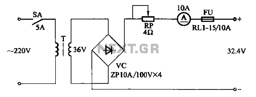
Full-wave rectifying circuit charging Adjustable
The adjustment potentiometer RP can modify the charging current.
The adjustment potentiometer, designated as RP, serves a critical role in regulating the charging current within an electronic circuit. This component is typically a variable resistor that allows for fine-tuning of the...