


LED Audio VU Meter
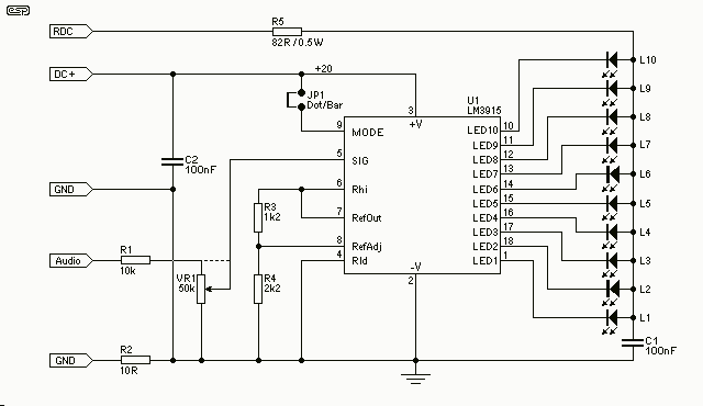
Description: This project is also an essential part of the expandable analyser to be published soon or perhaps eventually, and one meter circuit is used for each frequency band. There are many other uses for a simple LED VU meter. They are ideal as power meters on amplifiers, can be used with mixers including the high-quality mixer described in the project pages, preamps, and any other application where it is important to know the signal level. The circuit is completely conventional and is based on the application notes from National Semiconductor. The circuit is shown in Figure 1 and as you can see it uses a single IC and a few discrete components. There are two rectifier circuits so that the DC to the LEDs is almost unfiltered.
The described circuit functions as an LED VU meter, which provides visual feedback of audio signal levels across different frequency bands. This versatility allows it to be employed not only in audio mixing environments but also in amplifiers and preamplifiers, where monitoring signal strength is crucial. The design utilizes a single integrated circuit (IC) along with a minimal number of discrete components, making it efficient and cost-effective for various applications.
The circuit features two rectifier stages, which serve to convert the AC audio signals into DC levels that drive the LEDs. This arrangement ensures that the LED indicators provide a responsive visual representation of the audio signal's amplitude, allowing users to gauge levels accurately. The rectifiers are designed to minimize filtering, which enhances the responsiveness of the LEDs to rapid changes in signal level, making it particularly useful for dynamic audio signals.
The schematic likely includes connections for the input signal, power supply, and output to the LEDs. The IC may be responsible for processing the incoming audio signal and controlling the corresponding LED outputs based on the detected signal levels. The discrete components may include resistors and capacitors that help set the gain and response characteristics of the circuit, ensuring that it operates effectively across the intended frequency range.
In summary, this LED VU meter circuit is a practical solution for real-time audio level monitoring, making it an essential tool in any audio engineer's toolkit. Its straightforward design, based on proven application notes from National Semiconductor, ensures reliability and ease of integration into various audio systems.This project is also an essential part of the expandable analyser to be published soon (or perhaps "eventually"), and one meter circuit is used for each frequency band. There are many other uses for a simple LED VU meter. They are ideal as power meters on amplifiers, can be used with mixers (including the high quality mixer described in the project pages), preamps and any other application where it is important to know the signal level.
The circuit is completely conventional, and is based on the application notes from National Semiconductor. The circuit is shown in Figure 1 and as you can see it uses a single IC and a few discrete components.
There are two rectifier circuits so that the DC to the LEDs is almost unfiltered.
The described circuit functions as an LED VU meter, which provides visual feedback of audio signal levels across different frequency bands. This versatility allows it to be employed not only in audio mixing environments but also in amplifiers and preamplifiers, where monitoring signal strength is crucial. The design utilizes a single integrated circuit (IC) along with a minimal number of discrete components, making it efficient and cost-effective for various applications.
The circuit features two rectifier stages, which serve to convert the AC audio signals into DC levels that drive the LEDs. This arrangement ensures that the LED indicators provide a responsive visual representation of the audio signal's amplitude, allowing users to gauge levels accurately. The rectifiers are designed to minimize filtering, which enhances the responsiveness of the LEDs to rapid changes in signal level, making it particularly useful for dynamic audio signals.
The schematic likely includes connections for the input signal, power supply, and output to the LEDs. The IC may be responsible for processing the incoming audio signal and controlling the corresponding LED outputs based on the detected signal levels. The discrete components may include resistors and capacitors that help set the gain and response characteristics of the circuit, ensuring that it operates effectively across the intended frequency range.
In summary, this LED VU meter circuit is a practical solution for real-time audio level monitoring, making it an essential tool in any audio engineer's toolkit. Its straightforward design, based on proven application notes from National Semiconductor, ensures reliability and ease of integration into various audio systems.This project is also an essential part of the expandable analyser to be published soon (or perhaps "eventually"), and one meter circuit is used for each frequency band. There are many other uses for a simple LED VU meter. They are ideal as power meters on amplifiers, can be used with mixers (including the high quality mixer described in the project pages), preamps and any other application where it is important to know the signal level.
The circuit is completely conventional, and is based on the application notes from National Semiconductor. The circuit is shown in Figure 1 and as you can see it uses a single IC and a few discrete components.
There are two rectifier circuits so that the DC to the LEDs is almost unfiltered.
White LEDs Flashlight
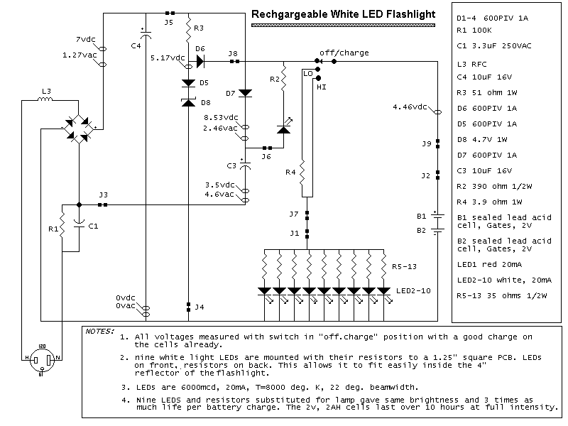
Here is a schematic of a rechargeable 9-LED flashlight using two Gates SLA cells and nine LEDs. It is as bright as when the single bulb was used, and lasts 3 times longer per charge. That is about 10 hours...
LED stepdown power supply
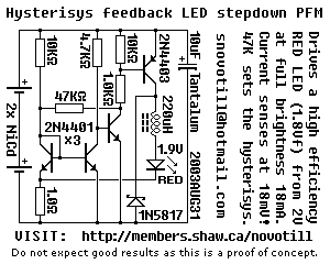
Below is a proof of concept circuit which needs improvement. The part values shown will run a high efficiency red LED with a Vf of 1.9V from only 2 nicads, right down to 2 volts. For a white LED you...
STEREO LED VU METER
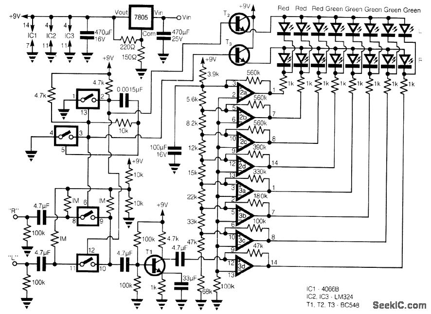
This circuit offers a cost-effective alternative to the LM3915 series LED displays. It utilizes a square-wave oscillator constructed with two CMOS analog switches, which alternately select the right and left channels for monitoring and display. The chosen signal is amplified...
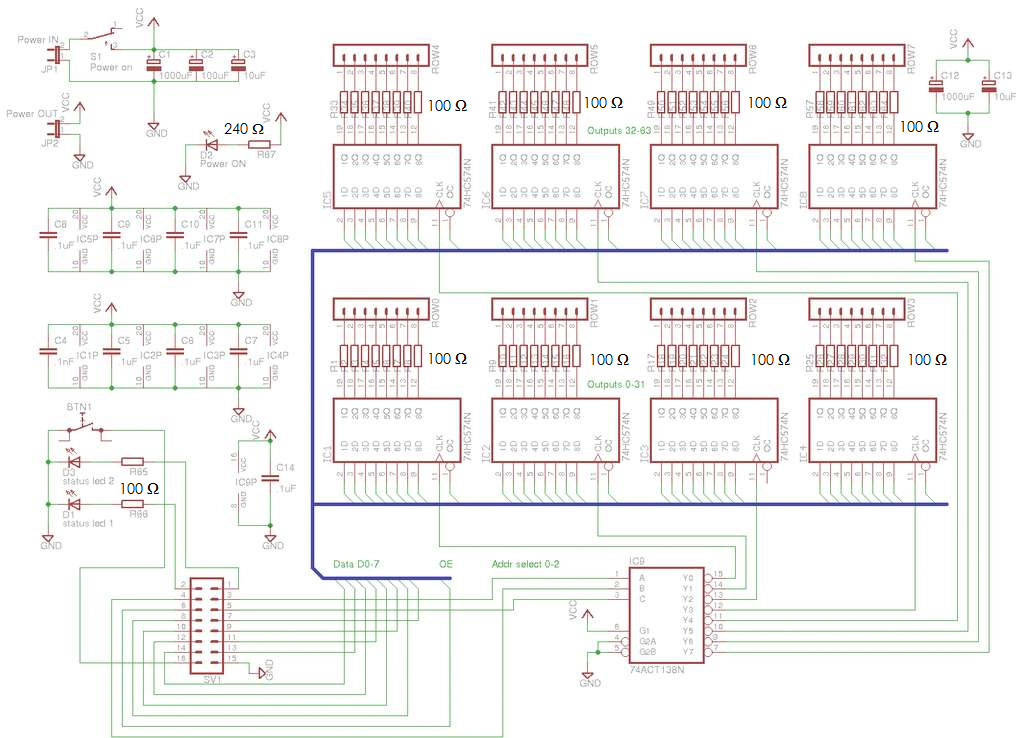
8x8x8 LED Cube
A total of 512 functional LEDs is required for the lattice assembly. These LEDs must be stable and bright. This section outlines the process for identifying faulty LEDs among the usable ones. Often, there are defective LEDs, particularly when purchased...
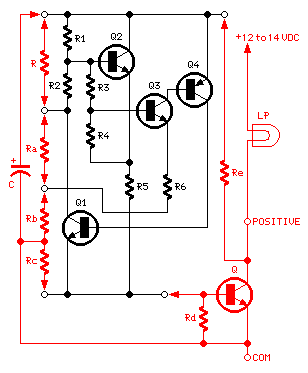
1.5V LED Flasher Oscillator
The 8-lead plastic mini-DIP LM3909 integrated circuit was developed by National Semiconductor in the mid-1970s. It is a monolithic oscillator specifically designed to flash Light Emitting Diodes (LEDs). By utilizing the timing capacitor for voltage boosting, it can deliver pulses...

Authentic Looking Knight Rider Led Project
The circuit features red lights that chase up and down on the front of the kit, with a pause of about one second between each sequence. Unlike other circuits that continuously pulse a decade counter, this design employs two 555...
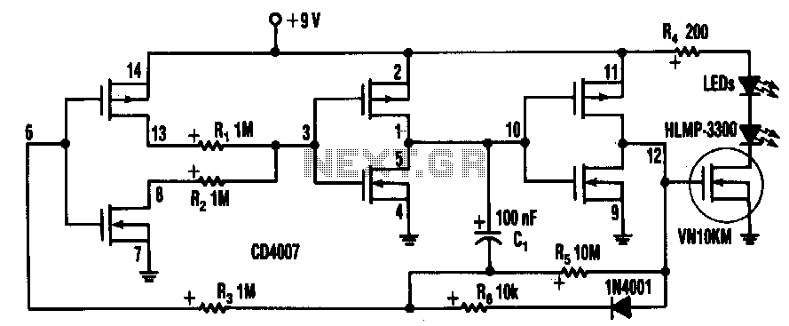
Three-year-led-flasher
Inserting two 1-MΩ resistors, R1 and R2, in the output stage of one of the circuit's inverters limits the current needed by the oscillator tone to more than a few pA. This circuit includes a CD4007 package, which contains three...
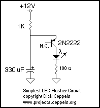
One transistor LED Flasher
This may be the simplest LED flasher circuit you can build, with the notable exclusion of LEDs with integrated flashing circuits. This might be a good replacement for the LM3909 in some applications. Take a close look. Only the emitter...
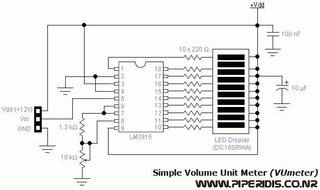
vu meter circuit
This is the simplest VU meter that can be constructed. It is based on a single integrated circuit. A volume unit (VU) meter, or standard volume indicator, is a device used to display the level of any voltage signal source,...