


led chasers
#LED
#PIC microcontroller
#sequential lighting
#light chaser
#Nite-Rider
#children's projects
#LED tricks
#lighting effects
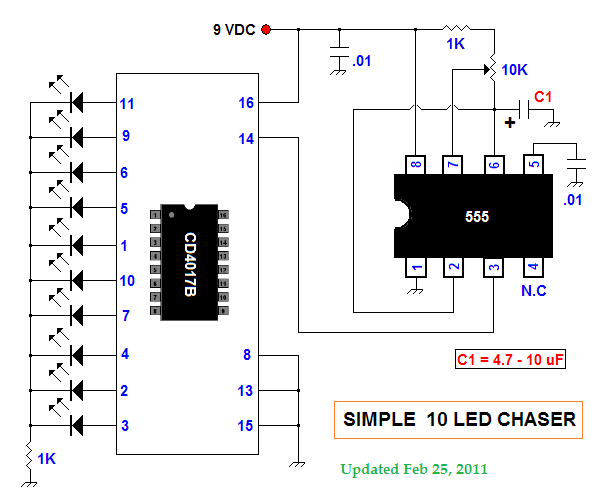
Description: This summer, several LED projects were constructed, including sequential LED chasers that operate from left to right and a Nite-Rider style that moves sequentially left, right, left, right, and so on. These projects are enjoyable for children to experiment with. Currently, there is experimentation with PIC microcontrollers to perform various LED effects. Numerous additional LED schematics can be found online through a Google search. LED projects are entertaining for both amateur radio operators and shortwave listeners.
LED projects utilizing microcontrollers, such as PICs, offer a wide range of possibilities for creating dynamic lighting effects. The sequential LED chaser circuit typically consists of an array of LEDs connected to the output pins of the microcontroller. A simple program controls the timing and sequence of turning the LEDs on and off, creating the appearance of movement. For instance, in a left-to-right chaser, the microcontroller activates each LED in succession, with a delay between each activation to give the illusion of movement.
In contrast, the Nite-Rider style chaser utilizes a more complex sequence where the LEDs alternate directions. This can be achieved by programming the microcontroller to first light the LEDs from left to right and then from right to left, creating a back-and-forth effect. The timing and duration of each segment can be adjusted to enhance the visual effect.
The use of PIC microcontrollers allows for flexibility in programming, enabling the incorporation of additional features such as adjustable speed, brightness control, and even patterns that can respond to external inputs like sound or light. For instance, a sound-activated LED chaser could utilize a microphone input to trigger the LED sequence based on ambient noise levels.
In terms of circuit design, the basic components include the microcontroller, resistors, and LEDs. The microcontroller's output pins connect to current-limiting resistors, which in turn connect to the LEDs. A power supply, typically a battery or DC power source, is used to provide the necessary voltage and current for the LEDs and the microcontroller. Proper attention must be given to the specifications of the LEDs and the microcontroller to ensure compatibility and prevent damage.
Overall, LED projects are not only entertaining but also serve as an excellent introduction to electronics and programming for enthusiasts of all ages. They provide hands-on experience with circuit design, coding, and troubleshooting, making them ideal for both educational purposes and hobbyist exploration.This summer I built several LED projects including sequential LED chasers (sequentially left to right) and also Nite-Rider style which go (sequentially left-right-left-right-etc) They are also a lot of fun for children to experiment with. Currently, I am experimenting with PIC microcontrollers to perform LED tricks Many more LED schematics c
an be found on the World Wide Web via a Google search. LED projects are great fun for both HAM`s and SWL`s alike
LED projects utilizing microcontrollers, such as PICs, offer a wide range of possibilities for creating dynamic lighting effects. The sequential LED chaser circuit typically consists of an array of LEDs connected to the output pins of the microcontroller. A simple program controls the timing and sequence of turning the LEDs on and off, creating the appearance of movement. For instance, in a left-to-right chaser, the microcontroller activates each LED in succession, with a delay between each activation to give the illusion of movement.
In contrast, the Nite-Rider style chaser utilizes a more complex sequence where the LEDs alternate directions. This can be achieved by programming the microcontroller to first light the LEDs from left to right and then from right to left, creating a back-and-forth effect. The timing and duration of each segment can be adjusted to enhance the visual effect.
The use of PIC microcontrollers allows for flexibility in programming, enabling the incorporation of additional features such as adjustable speed, brightness control, and even patterns that can respond to external inputs like sound or light. For instance, a sound-activated LED chaser could utilize a microphone input to trigger the LED sequence based on ambient noise levels.
In terms of circuit design, the basic components include the microcontroller, resistors, and LEDs. The microcontroller's output pins connect to current-limiting resistors, which in turn connect to the LEDs. A power supply, typically a battery or DC power source, is used to provide the necessary voltage and current for the LEDs and the microcontroller. Proper attention must be given to the specifications of the LEDs and the microcontroller to ensure compatibility and prevent damage.
Overall, LED projects are not only entertaining but also serve as an excellent introduction to electronics and programming for enthusiasts of all ages. They provide hands-on experience with circuit design, coding, and troubleshooting, making them ideal for both educational purposes and hobbyist exploration.This summer I built several LED projects including sequential LED chasers (sequentially left to right) and also Nite-Rider style which go (sequentially left-right-left-right-etc) They are also a lot of fun for children to experiment with. Currently, I am experimenting with PIC microcontrollers to perform LED tricks Many more LED schematics c
an be found on the World Wide Web via a Google search. LED projects are great fun for both HAM`s and SWL`s alike
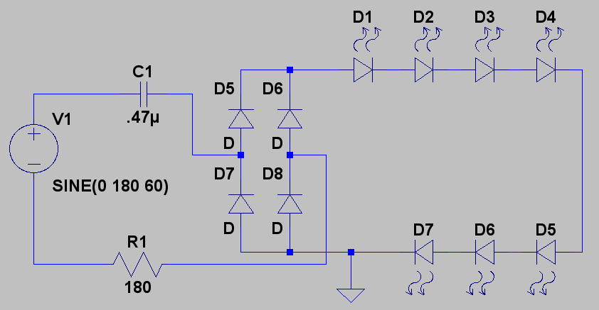
cf led lamp
Create LED lighting powered directly from the AC mains (120-Volt AC) due to the unavailability of inexpensive and safe enclosures for the circuitry. While collecting old failed CFLs for recycling, it was noted that the body of CFLs (also known...
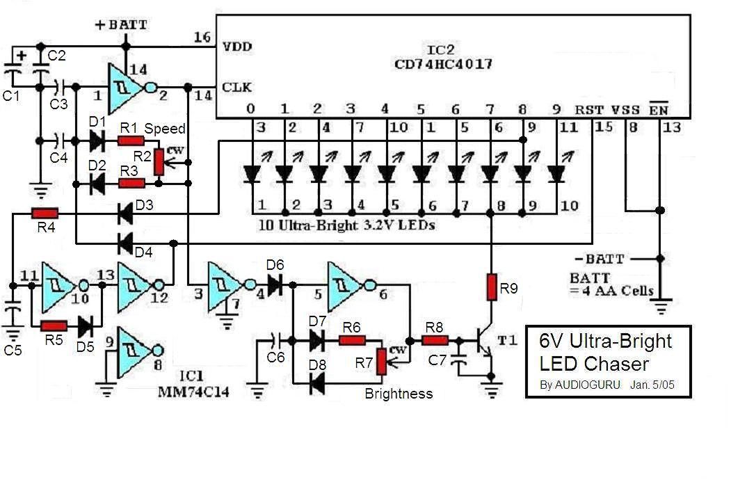
6V Ultra-Bright LED Chasers
This project involves a sequence of Ultra-Bright LEDs that light up briefly in a circular pattern, mounted on a CD. The LEDs flash for 15 milliseconds, followed by a one-second pause, creating a visually appealing effect. The brief flashes and...

NightRydazz
The device is designed to be mounted on the back wheel of a bicycle. It operates using a lithium-ion battery, allowing it to function independently while being attached to the spokes of the rear wheel. All components, with the exception...
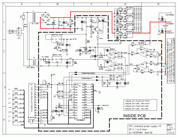
0-24v digital variable power supply circuit
The following circuit diagram depicts a variable power supply controlled by a PIC microcontroller. An LCD display is utilized to show the actual output current and voltage values. This digital power supply incorporates a push-button switch to adjust the output...
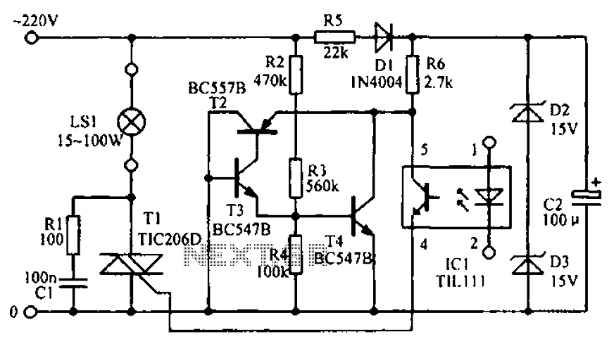
LED signal amplifying circuit diagram
The circuit diagram illustrates the LED signal amplification.
The LED signal amplification circuit is designed to enhance the output signal from an LED, allowing it to drive larger loads or to be interfaced with other electronic components effectively. The primary components...
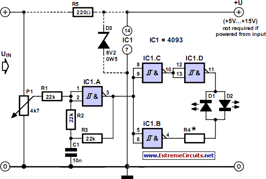
Two-LED Voltage Indicator
Many applications do not require the precision of a digital or analog (bar graph) indicator but still benefit from more than a simple low/high signal. An example is a battery charge level indicator in a car. This basic circuit, which...
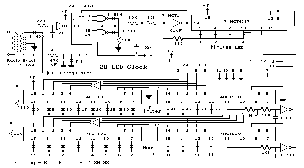
28 LED Clock Timer circuit
This is a programmable clock timer circuit that utilizes individual LEDs to display hours and minutes. Twelve LEDs can be arranged in a circular pattern to represent the 12 hours on a clock face, while an additional 12 LEDs can...
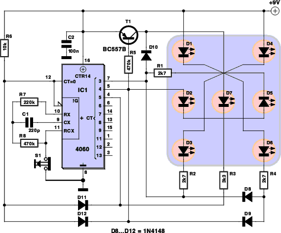
Dicing With LEDs circuit
Every dedicated DIY enthusiast creates their own electronic dice using LEDs as indicators. This eliminates the need to physically roll dice; simply pressing a button activates the electronic mechanism. The design incorporates safeguards to prevent manipulation for improved outcomes, ensuring...
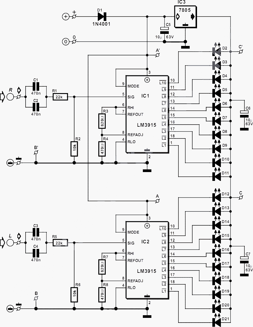
stereo led power vu meter
This circuit detects the AC audio voltage supplied to car radio loudspeakers and visually represents it as power using an LED bar graph, creating an appealing visual effect. It is designed to accommodate typical car radio output power ranges but...