


Led circuits
#LED
#AC power
#capacitor
#voltage drop
#current limiting
#diode
#resistor
#120V
#inrush current
#negative half cycle
Description: The circuit below illustrates powering one or two LEDs from the 120-volt AC line using a capacitor to drop the voltage and a small resistor to limit the inrush current. Since the capacitor must pass current in both directions, a small diode is connected in parallel with the LED to provide a path for the negative half cycle and to limit the reverse voltage across the LED. A second LED with reversed polarity may be substituted for the diode, or a tri-color LED could be used, which would appear orange with alternating current. The circuit is fairly efficient and draws only about half a watt from the line. The resistor value (1K / half watt) was chosen to limit the worst-case inrush current to about 150 mA, which drops to less than 30 mA in a millisecond as the capacitor charges. This appears to be a safe value, as the circuit has been switched on and off multiple times without damaging the LED. The 0.47 µF capacitor has a reactance of 5600 ohms at 60 Hz, so the LED current is about 20 mA half-wave, or 10 mA average. A larger capacitor will increase the current, and a smaller one will reduce it. The capacitor must be a non-polarized type with a voltage rating of 200 volts or more. The lower circuit is an example of obtaining a low regulated voltage from the AC line. The zener diode serves as a regulator and also provides a path for the negative half cycle current when it conducts in the forward direction. In this example, the output voltage is about 5 volts and will provide over 30 milliamps with about 300 millivolts of ripple. Caution is advised when operating any circuits connected directly to the AC line. The LED traffic light circuit controls six LEDs (red, yellow, and green) for both north/south and east/west directions. The timing sequence is generated using a CMOS 4017 decade counter and a 555 timer. Counter outputs 1 through 4 are wired ORed using four diodes so that the (Red - North/South) and (Green - East/West) LEDs will be on during the first four counts. The fifth count (pin 10) illuminates (Yellow - East/West) and (Red - North/South). Counts 6 through 9 are also wired ORed using diodes to control (Red - East/West) and (Green - North/South). Count 10 (pin 11) controls (Red - East/West) and (Yellow - North/South). The time period for the red and green lamps will be four times longer than for the yellow, and the complete cycle time can be adjusted with the 47K resistor. The eight 1N914 diodes could be substituted with a dual 4-input OR gate (CD4072). The 555 circuit below is a flashing bicycle light powered with four C, D, or AA cells (6 volts). Two sets of 20 LEDs will alternately flash at approximately 4.7 cycles per second using the RC values shown (4.7K for R1, 150K for R2, and a 1µF capacitor). Time intervals for the two lamps are about 107 milliseconds (T1, upper LEDs) and 104 milliseconds (T2, lower LEDs). Two transistors are used to provide additional current beyond the 200 mA limit of the 555 timer. A single LED is placed in series with the base of the PNP transistor so that the lower 20 LEDs turn off when the 555 output goes high during the T1 time interval. The high output level of the 555 timer is 1.7 volts less than the supply voltage. Adding the LED increases the forward voltage required for the PNP transistor to about 2.7 volts, so that the 1.7-volt difference from supply to the output is insufficient to turn on the transistor. Each LED is supplied with about 20 mA of current for a total of 220 mA. The circuit should work with additional LEDs up to about 40 for each group, or 81 total. The circuit will also work with fewer LEDs, allowing it to be assembled and tested with just five LEDs (two groups of two plus one) before adding the others. (74HC138 or 74HCT138) can be used to generate the popular "Night Rider" display. A Schmitt Trigger oscillator provides the clock signal for the counter, and the rate can be adjusted with the 500K potentiometer. Two additional Schmitt Trigger inverters can be employed to enhance the circuit's functionality.
The circuit design effectively utilizes a capacitive dropper to power LEDs directly from the high-voltage AC mains, ensuring that the components are rated appropriately to handle the voltage and current levels. The use of a non-polarized capacitor is crucial for bidirectional current flow, while the inclusion of a diode or a second LED safeguards against reverse voltage, protecting the primary LED from potential damage. The choice of a 1K resistor is a calculated decision to balance the initial inrush current with the steady-state operation, ensuring the longevity of the LED.
The traffic light circuit exemplifies a practical application of sequential logic using the CMOS 4017 counter, which allows for a visually effective and safe traffic control system. The timing adjustments facilitated by the 555 timer and the resistor provide flexibility in operation, allowing for customization based on specific requirements.
Moreover, the bicycle light circuit demonstrates the versatility of the 555 timer in low-power applications, where the use of transistors allows for higher current loads beyond the timer's native capabilities. The design is modular, permitting easy testing and expansion, while the Schmitt Trigger components ensure reliable operation of the clock signal, providing stable timing for the light sequences. Overall, this circuit showcases a range of practical electronic design techniques suitable for various applications in LED lighting and control systems.The circuit below illustrats powering a LED (or two) from the 120 volt AC line using a capacitor to drop the voltage and a small resistor to limit the inrush current. Since the capacitor must pass current in both directions, a small diode is connected in parallel with the LED to provide a path for the negative half cycle and also to limit the reve
rse voltage across the LED. A second LED with the polarity reversed may be subsituted for the diode, or a tri-color LED could be used which would appear orange with alternating current. The circuit is fairly efficient and draws only about a half watt from the line. The resistor value (1K / half watt) was chosen to limit the worst case inrush current to about 150 mA which will drop to less than 30 mA in a millisecond as the capacitor charges.
This appears be a safe value, I have switched the circuit on and off many times without damage to the LED. The 0. 47 uF capacitor has a reactance of 5600 ohms at 60 cycles so the LED current is about 20 mA half wave, or 10 mA average.
A larger capacitor will increase the current and a smaller one will reduce it. The capacitor must be a non-polarized type with a voltage rating of 200 volts or more. The lower circuit is an example of obtaining a low regulated voltage from the AC line. The zener diode serves as a regulator and also provides a path for the negative half cycle current when it conducts in the forward direction. In this example the output voltage is about 5 volts and will provide over 30 milliamps with about 300 millivolts of ripple.
Use caution when operating any circuits connected directly to the AC line. The LED traffic Light circuit controls 6 LEDs (red, yellow and green) for both north/south directions and east/west directions. The timing sequence is generated using a CMOS 4017 decade counter and a 555 timer. Counter outputs 1 through 4 are wire ORed using 4 diodes so that the (Red - North/South) and (Green - East/West) LEDs will be on during the first four counts.
The fifth count (pin 10) illuminates (Yellow - East/West) and (Red - North/South). Counts 6 through 9 are also wire ORed using diodes to control (Red - East/West) and (Green - North/South). Count 10 (pin 11) controls (Red - East/West) and (Yellow - North/South). The time period for the red and green lamps will be 4 times longer than for the yellow and the complete cycle time can be adjusted with the 47K resistor.
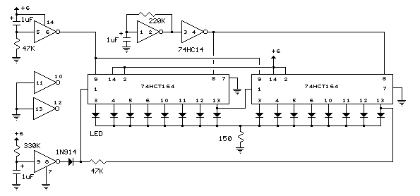
The eight 1N914 diodes could be subsituted with a dual 4 input OR gate (CD4072). The 555 circuit below is a flashing bicycle light powered with four C, D or AA cells (6 volts). Two sets of 20 LEDs will alternately flash at approximately 4. 7 cycles per second using RC values shown (4. 7K for R1, 150K for R2 and a 1uF capacitor). Time intervals for the two lamps are about 107 milliseconds (T1, upper LEDs) and 104 milliseconds (T2 lower LEDs). Two transistors are used to provide additional current beyond the 200 mA limit of the 555 timer. A single LED is placed in series with the base of the PNP transistor so that the lower 20 LEDs turn off when the 555 output goes high during the T1 time interval.
The high output level of the 555 timer is 1. 7 volts less than the supply voltage. Adding the LED increases the forward voltage required for the PNP transistor to about 2. 7 volts so that the 1. 7 volt difference from supply to the output is insufficient to turn on the transistor. Each LED is supplied with about 20 mA of current for a total of 220 mA. The circuit should work with additional LEDs up to about 40 for each group, or 81 total. The circuit will also work with fewer LEDs so it could be assembled and tested with just 5 LEDs (two groups of two plus one) before adding the others. (74HC138 or 74HCT138) to generate the popular "Night Rider" display. A Schmitt Trigger oscillator provides the clock signal for the counter and the rate can be adjusted with the 500K pot.
Two additional Schmitt Trigger invert
The circuit design effectively utilizes a capacitive dropper to power LEDs directly from the high-voltage AC mains, ensuring that the components are rated appropriately to handle the voltage and current levels. The use of a non-polarized capacitor is crucial for bidirectional current flow, while the inclusion of a diode or a second LED safeguards against reverse voltage, protecting the primary LED from potential damage. The choice of a 1K resistor is a calculated decision to balance the initial inrush current with the steady-state operation, ensuring the longevity of the LED.
The traffic light circuit exemplifies a practical application of sequential logic using the CMOS 4017 counter, which allows for a visually effective and safe traffic control system. The timing adjustments facilitated by the 555 timer and the resistor provide flexibility in operation, allowing for customization based on specific requirements.
Moreover, the bicycle light circuit demonstrates the versatility of the 555 timer in low-power applications, where the use of transistors allows for higher current loads beyond the timer's native capabilities. The design is modular, permitting easy testing and expansion, while the Schmitt Trigger components ensure reliable operation of the clock signal, providing stable timing for the light sequences. Overall, this circuit showcases a range of practical electronic design techniques suitable for various applications in LED lighting and control systems.The circuit below illustrats powering a LED (or two) from the 120 volt AC line using a capacitor to drop the voltage and a small resistor to limit the inrush current. Since the capacitor must pass current in both directions, a small diode is connected in parallel with the LED to provide a path for the negative half cycle and also to limit the reve
rse voltage across the LED. A second LED with the polarity reversed may be subsituted for the diode, or a tri-color LED could be used which would appear orange with alternating current. The circuit is fairly efficient and draws only about a half watt from the line. The resistor value (1K / half watt) was chosen to limit the worst case inrush current to about 150 mA which will drop to less than 30 mA in a millisecond as the capacitor charges.
This appears be a safe value, I have switched the circuit on and off many times without damage to the LED. The 0. 47 uF capacitor has a reactance of 5600 ohms at 60 cycles so the LED current is about 20 mA half wave, or 10 mA average.
A larger capacitor will increase the current and a smaller one will reduce it. The capacitor must be a non-polarized type with a voltage rating of 200 volts or more. The lower circuit is an example of obtaining a low regulated voltage from the AC line. The zener diode serves as a regulator and also provides a path for the negative half cycle current when it conducts in the forward direction. In this example the output voltage is about 5 volts and will provide over 30 milliamps with about 300 millivolts of ripple.
Use caution when operating any circuits connected directly to the AC line. The LED traffic Light circuit controls 6 LEDs (red, yellow and green) for both north/south directions and east/west directions. The timing sequence is generated using a CMOS 4017 decade counter and a 555 timer. Counter outputs 1 through 4 are wire ORed using 4 diodes so that the (Red - North/South) and (Green - East/West) LEDs will be on during the first four counts.
The fifth count (pin 10) illuminates (Yellow - East/West) and (Red - North/South). Counts 6 through 9 are also wire ORed using diodes to control (Red - East/West) and (Green - North/South). Count 10 (pin 11) controls (Red - East/West) and (Yellow - North/South). The time period for the red and green lamps will be 4 times longer than for the yellow and the complete cycle time can be adjusted with the 47K resistor.
The eight 1N914 diodes could be subsituted with a dual 4 input OR gate (CD4072). The 555 circuit below is a flashing bicycle light powered with four C, D or AA cells (6 volts). Two sets of 20 LEDs will alternately flash at approximately 4. 7 cycles per second using RC values shown (4. 7K for R1, 150K for R2 and a 1uF capacitor). Time intervals for the two lamps are about 107 milliseconds (T1, upper LEDs) and 104 milliseconds (T2 lower LEDs). Two transistors are used to provide additional current beyond the 200 mA limit of the 555 timer. A single LED is placed in series with the base of the PNP transistor so that the lower 20 LEDs turn off when the 555 output goes high during the T1 time interval.
The high output level of the 555 timer is 1. 7 volts less than the supply voltage. Adding the LED increases the forward voltage required for the PNP transistor to about 2. 7 volts so that the 1. 7 volt difference from supply to the output is insufficient to turn on the transistor. Each LED is supplied with about 20 mA of current for a total of 220 mA. The circuit should work with additional LEDs up to about 40 for each group, or 81 total. The circuit will also work with fewer LEDs so it could be assembled and tested with just 5 LEDs (two groups of two plus one) before adding the others. (74HC138 or 74HCT138) to generate the popular "Night Rider" display. A Schmitt Trigger oscillator provides the clock signal for the counter and the rate can be adjusted with the 500K pot.
Two additional Schmitt Trigger invert
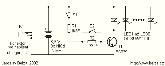
Powerful LED Flashlight circuit
Presented circuit is very simple. With more sampling, I refrained from using the converter and lamp designed for powering three NiCd or NiMH batteries. Because the voltage difference between the battery and the LED is very small, this arrangement is...
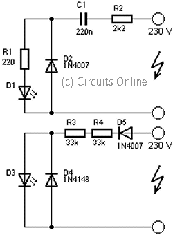
230volt led circuit
This circuit is used to power an LED with a voltage of 230V. The 230V must be reduced to meet the LED's voltage requirements. To achieve this, a circuit is necessary as described below.
The circuit designed to power an LED...
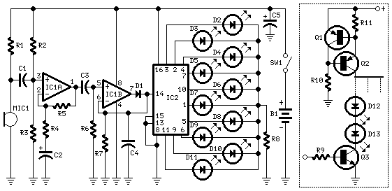
10 Dancing LEDs
The basic circuit illuminates up to ten LEDs in sequence, following the rhythm of music or speech picked up by a small microphone. The expanded version can drive up to ten strips, formed by up to five LEDs each, at...
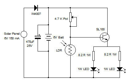
White LED Lamp with Solar Panel
In various industrial processes, it is essential to rotate a DC (or AC) motor both forward and reverse for a specified duration. Initially, the motor rotates forward (clockwise) for a certain period (approximately 2 to 3 minutes), then stops for...
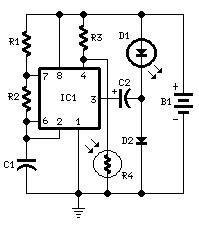
LED Night Lamp
This circuit is usable as a Night Lamp when a wall mains socket is not available to plug-in an ever running small neon lamp device. In order to ensure minimum battery consumption, one 1.5V cell is used, and a simple...
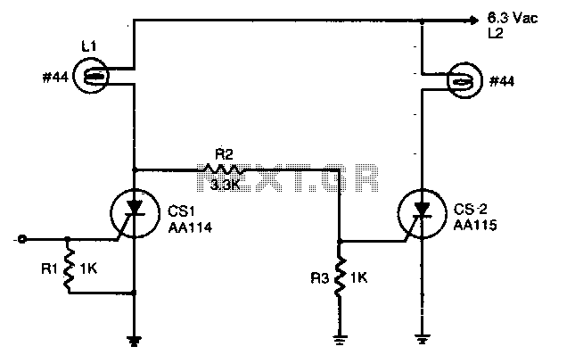
Complementary AC power switching
An input signal of less than 1 mA and 1V is required to switch on CS1. As long as this input signal is maintained, CS1 will conduct during each positive half-cycle of anode voltage, thereby energizing load L1 with half-wave...

Capacitor step-down DC power supply circuit
A capacitor step-down DC power supply circuit is presented. This circuit eliminates the need for power transformers, utilizing capacitive voltage drop rectification and regulation, which significantly reduces the overall size of the circuit. The circuit includes a capacitor step-down component,...
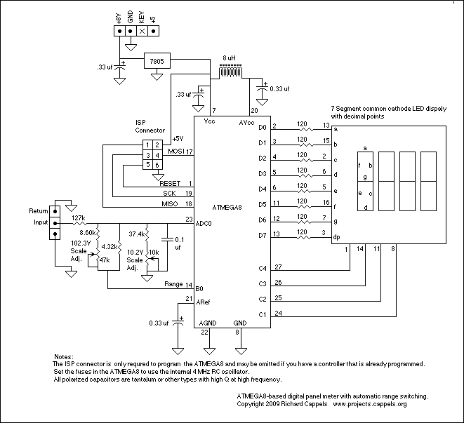
LED Digital Panel Meter
To explain in a little more detail, using the ATMEGA8's internal 2.5 volt band gap reference means that by using a resistive divider ahead of the A-to-D converter, the input could be scaled such that any voltage range from 0...
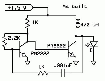
LED Boost Circuit
The completed board may be driven by voltages between 0.8 and 3 Volts. While the basic design goal was candle-like light from a single cell, the values used were chosen to allow safe operation from 3 Volts so you can,...