


LED tester circuit
#LED tester
#opamp
#LM358
#current control
#power supply
#jumper
#electrolytic capacitor
#voltage measurement
#0-30mA range
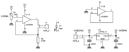
Description: This led tester uses a power switched op-amp. The control range is about 0-30mA. Thus, all test and standard LEDs, the voltage across the LED to read. The power supply is an example lab power supply at least 15V, 12V adapter if a U2 expires. Then put a jumper between pins 1 and 3 and use a 10uF electrolytic capacitor for C1. The LM358 is only half used; the other half is to shut down the mass.
Adjustment: Set a mA meter between A and K and adjust the power off with R1 for normal LEDs at 20mA. This current value is the normal stress according to the datasheet on the LED. This tester can also be used as a LED dimmer, but there is little or no difference between 15 and 30mA.
R1 = 100k trimming
R2 = 270Ω 1/4W
C1 = 100nF
C2 = 100nF
U1 = LM358N
U2 = 78L12
J1 and J2 = 2 print pins or pin headers
This LED tester circuit utilizes an LM358 operational amplifier (op-amp) configured as a power switch to control the current flowing through the LED under test. The circuit is designed to operate within a control range of approximately 0 to 30 mA, which accommodates a variety of standard LEDs. The power supply requirements are specified as a minimum of 15V, with the option of using a 12V adapter if the voltage regulator (U2, 78L12) is not operational.
The LM358 is a dual op-amp, but in this configuration, only one half is utilized for the current control function, while the other half is employed to facilitate a shutdown feature, enhancing the circuit's safety and usability. The circuit includes a jumper (J1) that connects pins 1 and 3 of the LM358, which is essential for the operation of the current control mechanism.
Capacitor C1, rated at 10 µF, is critical for stabilizing the power supply to the op-amp, ensuring reliable performance. Additionally, two 100 nF capacitors (C2) are included, likely for decoupling or filtering purposes, contributing to the overall stability of the circuit.
For calibration, a milliampere meter is connected between points A and K to monitor the current through the LED. Resistor R1, a 100 kΩ trimming potentiometer, allows for precise adjustment of the current, facilitating the setting of a nominal operating current of 20 mA, which is considered standard for many LEDs according to their datasheets. Resistor R2, specified as 270Ω with a 1/4W rating, is used in conjunction with R1 to define the current range.
The circuit also has the capability to function as a LED dimmer; however, it is noted that there may be minimal perceived difference in brightness between the current settings of 15 mA and 30 mA. The inclusion of pin headers (J1 and J2) facilitates easy connections and enhances the modularity of the circuit, allowing for straightforward integration into various testing setups.This ledtester uses as a power switched opamp. The control range is about 0-30mA. Thus, all test and standard LEDs, the voltage across the LED to read. The power supply is an example labvoeding at least 15V, 12V adapter if you're a U2 expires. Then put a jumper between pins 1 and 3 and use a 10uF electrolytic capacitor for C1. The LM358 is only half used the other half to the mass shut down. Adjustment: Set a mA meter between A and K and adjust the power off with R1 for normal LEDs is 20mA. This current value is the normal stress according datasheet on the LED may also be seen. This tester can also be used as leddimmer, but there is little or no difference between 15 and 30mA. R1 = 100k trimming R2 = 270? 1/4W C1 = 100nF C2 = 100nF U1 = LM358N U2 = 78L12 J1 and J2 = 2 print pins or pin headers
Adjustment: Set a mA meter between A and K and adjust the power off with R1 for normal LEDs at 20mA. This current value is the normal stress according to the datasheet on the LED. This tester can also be used as a LED dimmer, but there is little or no difference between 15 and 30mA.
R1 = 100k trimming
R2 = 270Ω 1/4W
C1 = 100nF
C2 = 100nF
U1 = LM358N
U2 = 78L12
J1 and J2 = 2 print pins or pin headers
This LED tester circuit utilizes an LM358 operational amplifier (op-amp) configured as a power switch to control the current flowing through the LED under test. The circuit is designed to operate within a control range of approximately 0 to 30 mA, which accommodates a variety of standard LEDs. The power supply requirements are specified as a minimum of 15V, with the option of using a 12V adapter if the voltage regulator (U2, 78L12) is not operational.
The LM358 is a dual op-amp, but in this configuration, only one half is utilized for the current control function, while the other half is employed to facilitate a shutdown feature, enhancing the circuit's safety and usability. The circuit includes a jumper (J1) that connects pins 1 and 3 of the LM358, which is essential for the operation of the current control mechanism.
Capacitor C1, rated at 10 µF, is critical for stabilizing the power supply to the op-amp, ensuring reliable performance. Additionally, two 100 nF capacitors (C2) are included, likely for decoupling or filtering purposes, contributing to the overall stability of the circuit.
For calibration, a milliampere meter is connected between points A and K to monitor the current through the LED. Resistor R1, a 100 kΩ trimming potentiometer, allows for precise adjustment of the current, facilitating the setting of a nominal operating current of 20 mA, which is considered standard for many LEDs according to their datasheets. Resistor R2, specified as 270Ω with a 1/4W rating, is used in conjunction with R1 to define the current range.
The circuit also has the capability to function as a LED dimmer; however, it is noted that there may be minimal perceived difference in brightness between the current settings of 15 mA and 30 mA. The inclusion of pin headers (J1 and J2) facilitates easy connections and enhances the modularity of the circuit, allowing for straightforward integration into various testing setups.This ledtester uses as a power switched opamp. The control range is about 0-30mA. Thus, all test and standard LEDs, the voltage across the LED to read. The power supply is an example labvoeding at least 15V, 12V adapter if you're a U2 expires. Then put a jumper between pins 1 and 3 and use a 10uF electrolytic capacitor for C1. The LM358 is only half used the other half to the mass shut down. Adjustment: Set a mA meter between A and K and adjust the power off with R1 for normal LEDs is 20mA. This current value is the normal stress according datasheet on the LED may also be seen. This tester can also be used as leddimmer, but there is little or no difference between 15 and 30mA. R1 = 100k trimming R2 = 270? 1/4W C1 = 100nF C2 = 100nF U1 = LM358N U2 = 78L12 J1 and J2 = 2 print pins or pin headers
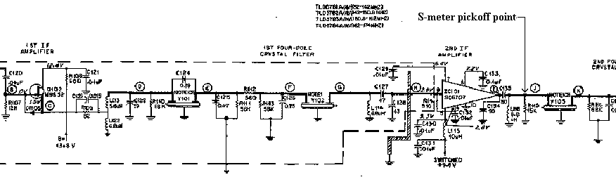
Motorola Micor S-meter Driver
The artwork style of the operational amplifier and the meter face suggests that it is an ACC design from an old issue of ACC Notes. The second image was scanned, and the text below was written from scratch. If the...
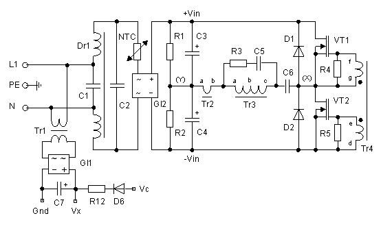
250 Watt PC power Supply
Up to 10 A continuous output current, or operation with 50 % ESD and 18 A peak current are possible without a fan if sufficient natural air flow is present and the ambient temperature does not exceed 30 °C. A...
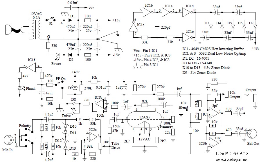
Tube Mic Pre-Amp
This is a simple audio microphone preamplifier circuit based on a single IC, the LM358. The circuit is straightforward, cost-effective, and easy to construct. The component parts list includes: R1, R3, R4 = 10K ohms, R2 = 1K ohm, R5...
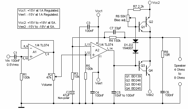
Opamp Based Power Amplifier
The amplifier is based on the commonly used class-AB complementary power amplifier with compound pair output transistors. The system uses a TL074 quad opamp to drive the output transistors. As can be seen from figure 1, A2 is used to...
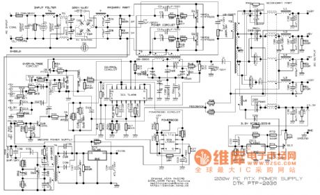
Switching Regulator Circuit
This example presents a switch DC regulated power supply circuit designed for buck-mode +5V applications. It consists of a power supply circuit, an impulsator, a voltage sampling or pulse width modulation circuit, and a buffering driver circuit, as illustrated in...
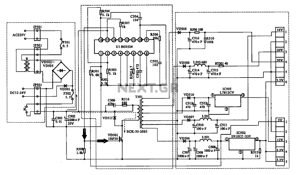
Changhong DVB-2000 digital satellite receiver switching power supply circuit
The Changhong DVB-2000 digital satellite receiver features a switching power supply circuit. This circuit primarily comprises a power input section, an oscillation switching circuit, and a DC output section. The power input circuit receives 22V AC from a step-down transformer,...
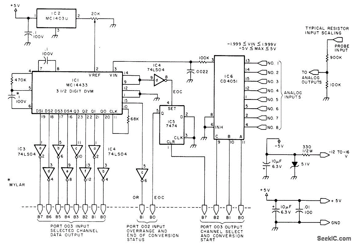
EIGHT CHANNEL COMPUTERIZED 3SUP1 SUP SUB2 SUB DIGIT_VM
Displays up to eight different DC voltages on a CRT terminal of a microprocessor under keyboard control, using BASIC commands and a BASIC routine provided in the article. Utilizes a modified Motorola MC14433 dual-lamp integrating analog-to-digital converter. An unknown voltage...
Battery charger or Power Supply 14 volt 4 ampere
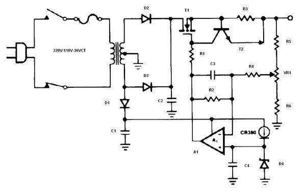
The schematic diagram originates from a circuit designed as a battery charger/power supply with an output of 14V and a maximum current of 4A, utilizing the VN64GA MOSFET. This high-performance battery charger is specifically engineered for gelled electrolyte lead-acid batteries,...
Loudness control
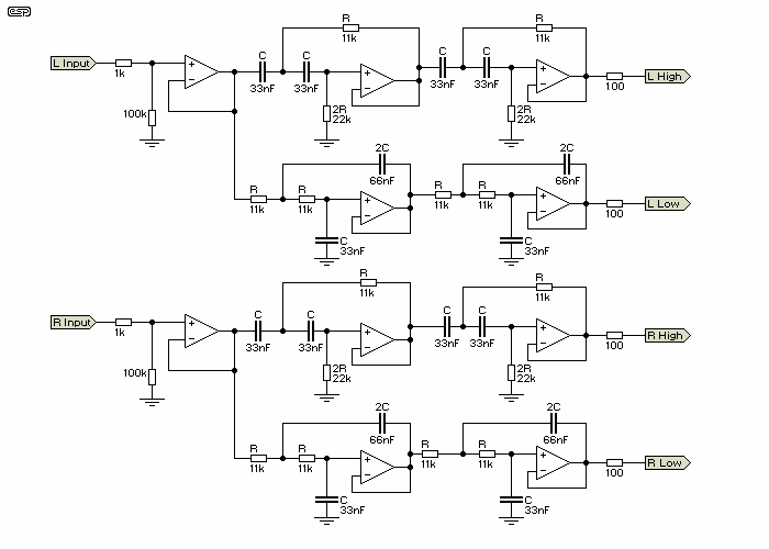
An operational amplifier such as the NE5532 should be used. The desired frequency must be calculated for each block: one for flat, one for bass, and one for high frequencies. It is important to include a buffer at the first...