


Light-controlled-lamp-switch
#light-controlled
#lamp switch
#CdS photocell
#wireless
#transistor
#automatic switching
#stage lighting
#simple circuit
#inexpensive
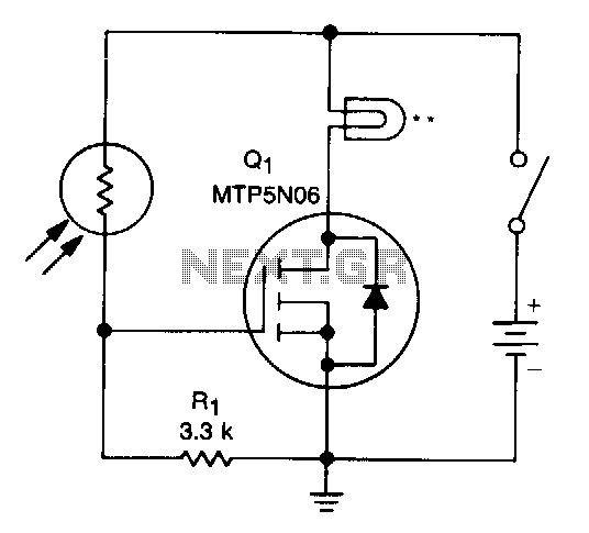
Description: A school drama required lamps that automatically turned on and off in sync with the spotlights. The lamp switching system needed to be wireless, durable, reliable, simple, and cost-effective. With the stage and spotlights turned off, minimal light reaches the CdS photocell, resulting in its internal resistance being several megohms. This high resistance keeps the gate of transistor Q1 at nearly zero volts, thus keeping it off. When a spotlight or stage light illuminates the photocell, its resistance decreases to several hundred ohms, which raises the gate voltage of Q1, turning it on and supplying power to the lamp.
The described circuit utilizes a CdS photocell as a light-sensitive resistor that plays a critical role in controlling the operation of a lamp in response to the illumination from stage lights. The circuit is designed to operate in a wireless configuration, which enhances its usability in a theatrical setting where mobility and ease of installation are paramount.
In the off state, the high resistance of the CdS photocell ensures that the gate voltage of transistor Q1 remains low, preventing any current from flowing to the lamp. This condition is ideal when the stage is dark, as it conserves energy and minimizes unnecessary light emission. The use of a high-value resistor (Rl) in conjunction with the photocell is crucial, as it establishes a stable condition for the gate of Q1, ensuring that the transistor remains in the off state until it is activated by an adequate light source.
When the stage lights are turned on, the illumination from the spotlights causes a significant drop in the resistance of the CdS photocell. This transition allows for an increase in gate voltage at Q1, transitioning the transistor into its active state. As Q1 turns on, it permits current to flow through the lamp, illuminating it in synchronization with the stage lighting.
This design emphasizes simplicity and cost-effectiveness, as it relies on readily available components and does not require complex circuitry. The wireless aspect of the system can be achieved through the use of RF modules or other wireless communication methods, allowing for remote control and operation without the need for extensive wiring.
Overall, this schematic provides a functional and efficient solution for managing stage lighting in a school drama, ensuring that the lamps operate seamlessly in conjunction with the spotlights, enhancing the overall theatrical experience.A school drama needed lamps that automatically turned on and off when spot lights did the same. Lamp switching had to be wireless, durable, dependable, simple and inexpensive. With stage and spot lights off, very little light falls on the CdS photocell, so its internal resistance is several megohms and Rl keeps the gate of Ql at nearly zero volts, which keeps it off. When a spot or stage light hits the photocell, its resistance drops to several hundred ohms, raising Ql"s gate voltage, which turns it on and applies power to the lamp.
The described circuit utilizes a CdS photocell as a light-sensitive resistor that plays a critical role in controlling the operation of a lamp in response to the illumination from stage lights. The circuit is designed to operate in a wireless configuration, which enhances its usability in a theatrical setting where mobility and ease of installation are paramount.
In the off state, the high resistance of the CdS photocell ensures that the gate voltage of transistor Q1 remains low, preventing any current from flowing to the lamp. This condition is ideal when the stage is dark, as it conserves energy and minimizes unnecessary light emission. The use of a high-value resistor (Rl) in conjunction with the photocell is crucial, as it establishes a stable condition for the gate of Q1, ensuring that the transistor remains in the off state until it is activated by an adequate light source.
When the stage lights are turned on, the illumination from the spotlights causes a significant drop in the resistance of the CdS photocell. This transition allows for an increase in gate voltage at Q1, transitioning the transistor into its active state. As Q1 turns on, it permits current to flow through the lamp, illuminating it in synchronization with the stage lighting.
This design emphasizes simplicity and cost-effectiveness, as it relies on readily available components and does not require complex circuitry. The wireless aspect of the system can be achieved through the use of RF modules or other wireless communication methods, allowing for remote control and operation without the need for extensive wiring.
Overall, this schematic provides a functional and efficient solution for managing stage lighting in a school drama, ensuring that the lamps operate seamlessly in conjunction with the spotlights, enhancing the overall theatrical experience.A school drama needed lamps that automatically turned on and off when spot lights did the same. Lamp switching had to be wireless, durable, dependable, simple and inexpensive. With stage and spot lights off, very little light falls on the CdS photocell, so its internal resistance is several megohms and Rl keeps the gate of Ql at nearly zero volts, which keeps it off. When a spot or stage light hits the photocell, its resistance drops to several hundred ohms, raising Ql"s gate voltage, which turns it on and applies power to the lamp.
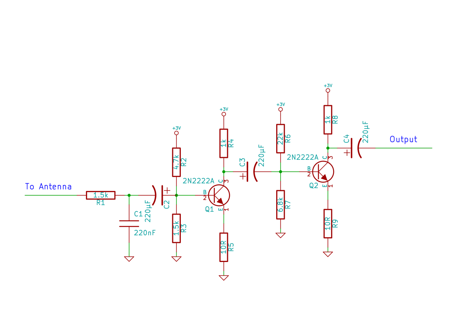
Simple Transistor Amplifier Circuit Schematic and Explanation
This circuit does not function as effectively as it could. It was created when the designer had a limited understanding of circuit design. An improved schematic will be developed and posted later, featuring a better design. The schematic indicates "antenna,"...
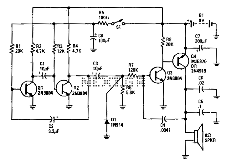
Electronic-bird-chirper
Transistors Q1 and Q2 form the two halves of a free-running multivibrator, with the frequency determined by the voltage across capacitor C8. This capacitor is charged and discharged by the operation of switch S1. Transistors Q3 and Q4 constitute a...
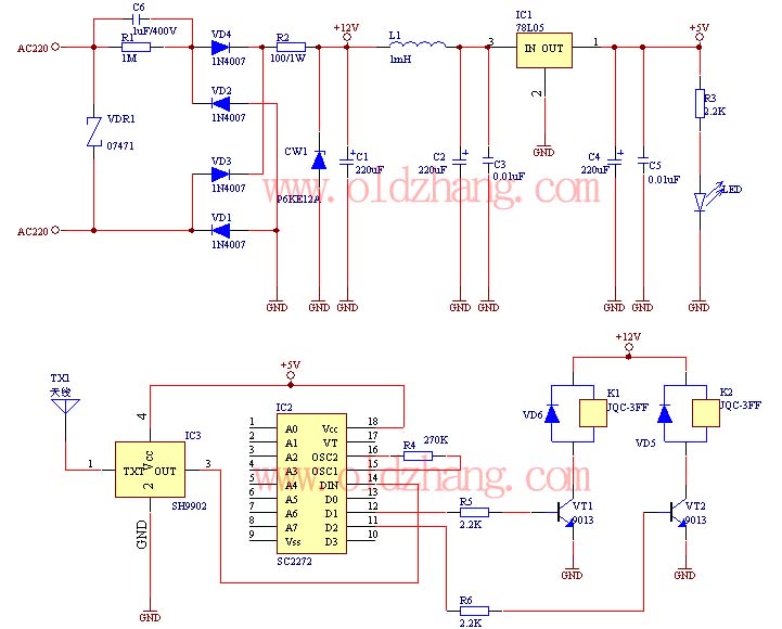
Road remote control switch production
The production of this wireless remote control switch is relatively straightforward. All component parameters have been tested and verified. The installation of the reader component parameters can be completed during production, including the soldering of resistive and capacitive components onto...
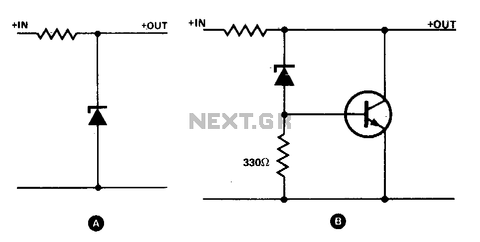
Transistor increases zener rating
The simple zener shunt in configuration A may not handle sufficient current if the zener diode available is of low wattage. A power transistor will perform most of the work for the zener as illustrated in configuration B. Once the...
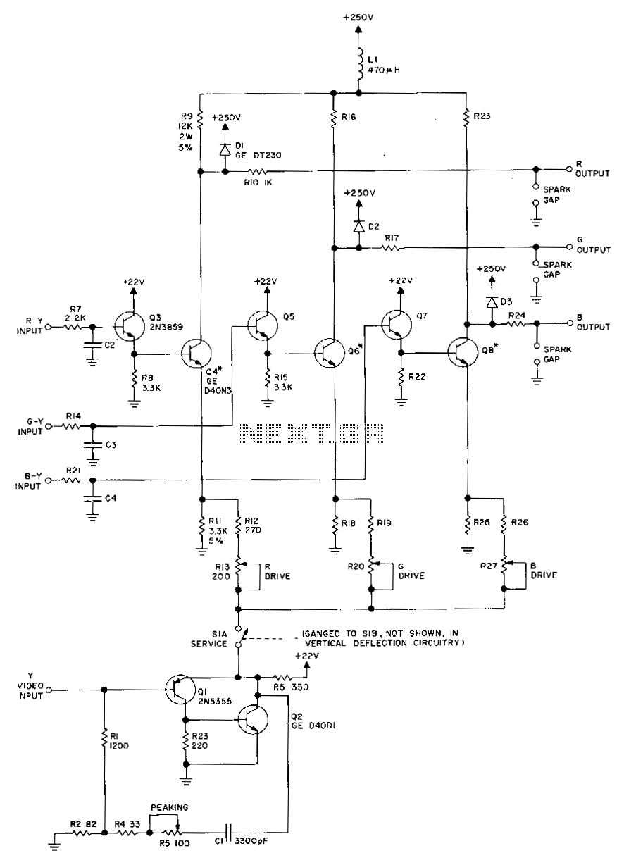
Rgb-video-amplifier
Transistors Q1 and Q2, along with their associated components, provide a low-impedance output necessary for driving the output stages. They enhance gain at high frequencies and improve video peaking for better transient response. Emitter followers Q3, Q5, and Q7 offer...
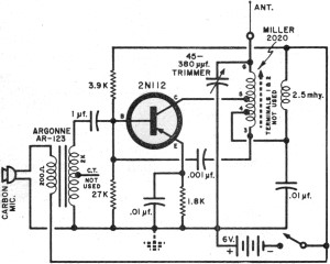
Transistor Circuits
It had been a little over a decade since the invention of the transistor when this article appeared in the August 1959 edition of Popular Electronics. Transistors were still a mystery to many, including engineers, technicians, and hobbyists. Author James...
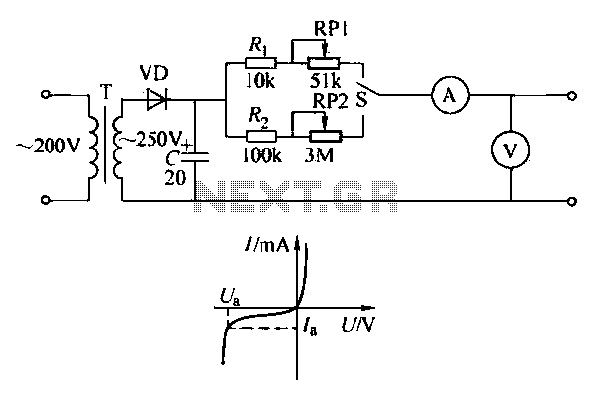
Transistor circuit of a pressure gauge
To ensure proper operation of the transistor in a circuit, it is essential to measure the reverse breakdown voltage of the transistor. This is particularly important for tubes with high reverse breakdown voltage requirements, such as those used in OCL...
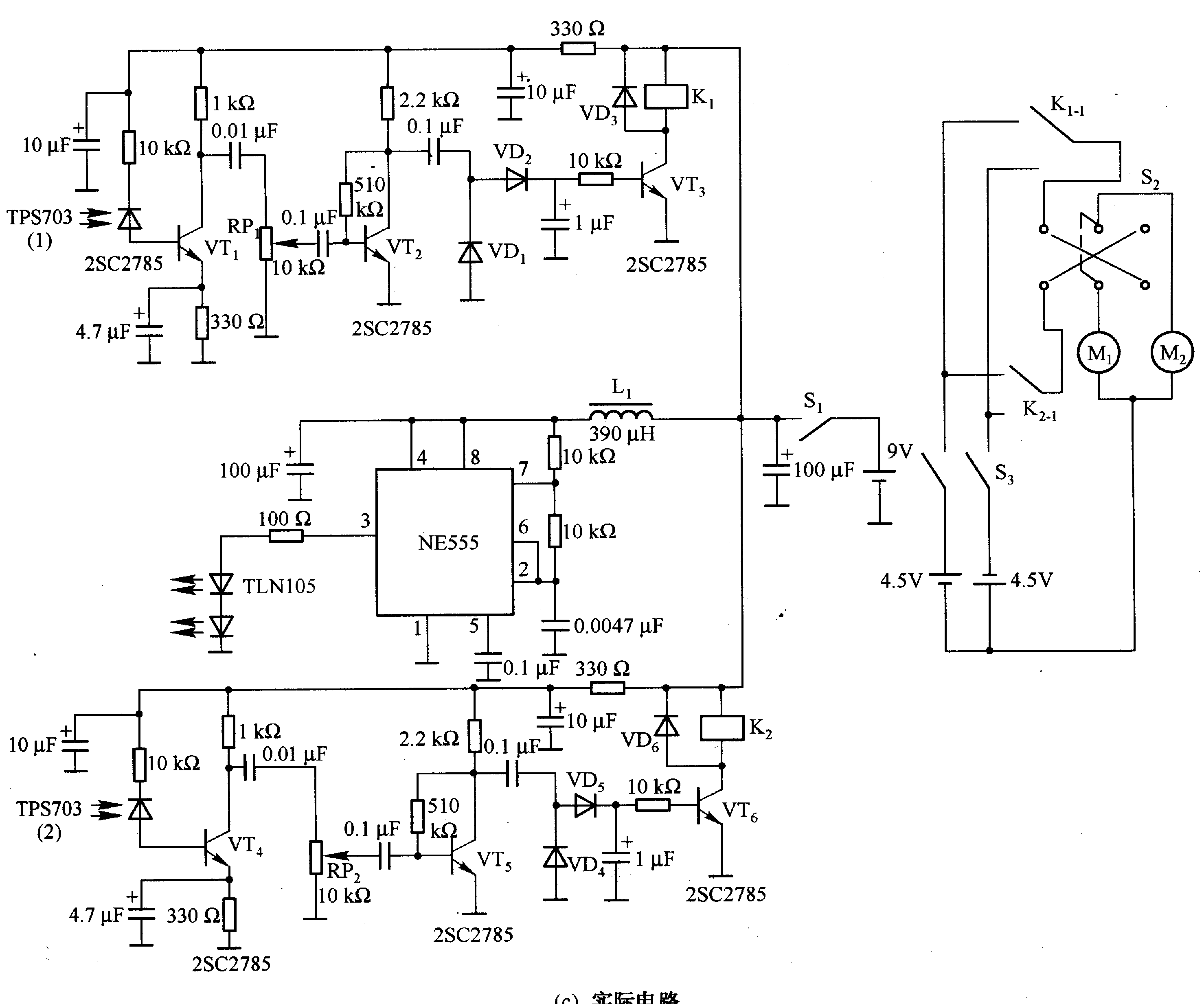
Robot control circuit composed of transistor and NE555
Figure 2-33 (a) illustrates the schematic diagram of a robot approaching an object. When no objects are detected in front of the robot, it moves forward in a straight line. If an object is detected on the left or right...
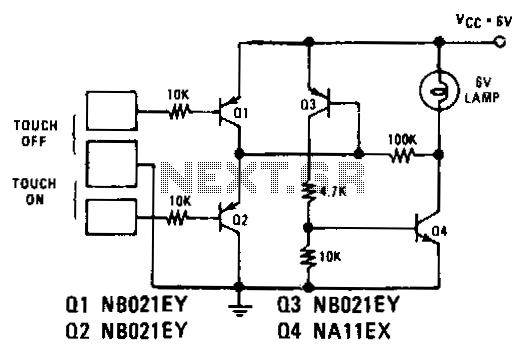
Touch-on-off-electronic-switch
Transistors Q1 and Q2 control latches Q3 and Q4 to switch on the lamp. A high resistance from touching the electrode biases Q1 or Q2 on, setting or resetting the latch.
In this circuit, transistors Q1 and Q2 function as input...