


Light-modulator
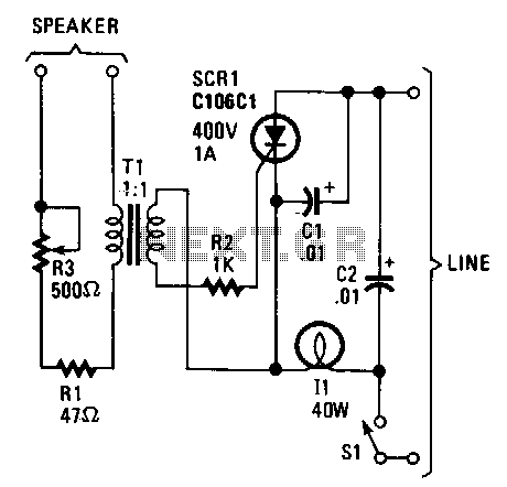
Description: The lights appear to synchronize with the music. Line-voltage lamps rated between 40 to 100 watts function effectively. The current for the lamp is controlled by a silicon-controlled rectifier (SCR). When low-level audio signals are present across transformer T1, SCR1 remains in a non-conductive state. However, a louder audio signal activates SCR1, causing the lamp to illuminate and respond to the sound. Additionally, since SCR1 operates with alternating current, the rectifier exits the avalanche condition when the gate current is low. The potentiometer R3 allows for adjustment of the power supplied to transformer T1, ensuring that under normal operating volume, SCR1 is triggered repeatedly, except during quieter segments.
The circuit utilizes a silicon-controlled rectifier (SCR) to control the illumination of line-voltage lamps in response to audio signals. The system is designed to enhance the visual experience of music by synchronizing the lighting effects with sound levels. The main components include an SCR (SCR1), a transformer (T1), a potentiometer (R3), and the line-voltage lamps rated between 40 to 100 watts.
In operation, when low-level audio signals are detected across transformer T1, SCR1 remains off, preventing current from flowing to the lamps. This ensures that the lamps do not activate during softer musical passages. As the audio volume increases, the gate current of SCR1 reaches a threshold that allows it to conduct. This conduction enables current to flow through the lamps, causing them to illuminate in accordance with the intensity of the sound.
The inclusion of the potentiometer R3 is crucial for adjusting the sensitivity of the SCR's triggering mechanism. By varying the resistance, the amount of power delivered to transformer T1 can be modified, thus influencing the gate current of SCR1. This feature allows for fine-tuning of the system to accommodate different audio environments and desired lighting effects. Consequently, during normal audio levels, SCR1 will repeatedly trigger, creating a dynamic lighting effect that enhances the overall auditory experience.
The design is well-suited for applications in entertainment venues, home theaters, or any setting where synchronized lighting effects can elevate the ambiance. Proper implementation of this circuit requires careful consideration of component ratings and characteristics to ensure reliable performance and safety.The lights seem to dance in time with the music. Line-voltage lamps of about 40 to 100 W do nicely. The current for the lamp is from an SCR. When low-level audio is present across Tl, SCR1 is not triggered into conduction. A louder signal, however, triggers the SCR so that the lamp lights and follows the sounds. Since SCR1 is operated by an alternating current, the rectifier moves out of the avalanche condition when the gate current is low. Potentiometer R3 lets you adjust the power reaching transformer T1, so that with normal operating volume, SCR1 triggers again and again, except during quiet passages.
The circuit utilizes a silicon-controlled rectifier (SCR) to control the illumination of line-voltage lamps in response to audio signals. The system is designed to enhance the visual experience of music by synchronizing the lighting effects with sound levels. The main components include an SCR (SCR1), a transformer (T1), a potentiometer (R3), and the line-voltage lamps rated between 40 to 100 watts.
In operation, when low-level audio signals are detected across transformer T1, SCR1 remains off, preventing current from flowing to the lamps. This ensures that the lamps do not activate during softer musical passages. As the audio volume increases, the gate current of SCR1 reaches a threshold that allows it to conduct. This conduction enables current to flow through the lamps, causing them to illuminate in accordance with the intensity of the sound.
The inclusion of the potentiometer R3 is crucial for adjusting the sensitivity of the SCR's triggering mechanism. By varying the resistance, the amount of power delivered to transformer T1 can be modified, thus influencing the gate current of SCR1. This feature allows for fine-tuning of the system to accommodate different audio environments and desired lighting effects. Consequently, during normal audio levels, SCR1 will repeatedly trigger, creating a dynamic lighting effect that enhances the overall auditory experience.
The design is well-suited for applications in entertainment venues, home theaters, or any setting where synchronized lighting effects can elevate the ambiance. Proper implementation of this circuit requires careful consideration of component ratings and characteristics to ensure reliable performance and safety.The lights seem to dance in time with the music. Line-voltage lamps of about 40 to 100 W do nicely. The current for the lamp is from an SCR. When low-level audio is present across Tl, SCR1 is not triggered into conduction. A louder signal, however, triggers the SCR so that the lamp lights and follows the sounds. Since SCR1 is operated by an alternating current, the rectifier moves out of the avalanche condition when the gate current is low. Potentiometer R3 lets you adjust the power reaching transformer T1, so that with normal operating volume, SCR1 triggers again and again, except during quiet passages.
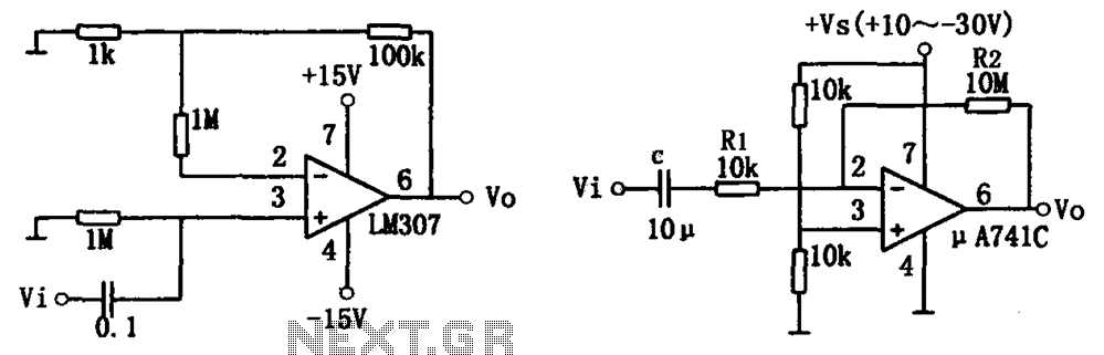
Simple audio amplifier LM307 A741
The simple audio amplifier circuit is illustrated in the figure. Utilizing an integrated op-amp configuration, this audio amplifier is stable and allows for easy negative feedback, facilitating the achievement of equalization characteristics. Additionally, the crosstalk between channels is minimal, making...
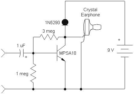
Audio High Gain Crystal Earphone Amplifier
This simple, one-transistor amplifier provides a voltage gain of over 1000 (60 dB) for an active aerial impedance crystal earphone. The gain is achieved by replacing the standard load resistor with a constant-current diode that supplies 1/2 mA while exhibiting...
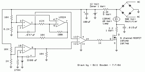
Sunrise Lamp
This circuit gradually illuminates a 120VAC lamp over an approximate 20-minute period. A bridge rectifier provides 120V DC to the MOSFET and the 60-watt lamp. A 6.2K, 5-watt resistor and a zener diode are employed to reduce the voltage to...
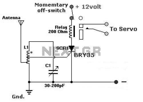
Very Simple Radio Control (R/C)
The diagram illustrates a simple and efficient receiver designed for controlling garage doors, starter motors, alarms, warning systems, and various other applications. The SCR utilized in this circuit features an exceptionally low trigger current of 30 µA.
The circuit operates as...
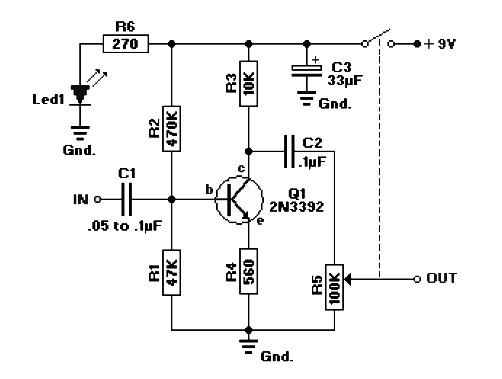
Audio Booster
The circuit diagram represents a booster for an audio application. It features a linear potentiometer R5 with a resistance of 100K ohms, which includes an on/off switch. The capacitor C1 should be selected with a value between 0.05 µF and...

Audio Fader
In this circuit, Q1 serves as a simple amplifier with gain control provided by a variable emitter resistance supplied by FET Q2. When switch SI is in the up position, capacitor C3 discharges through resistor R5, resulting in a decrease...
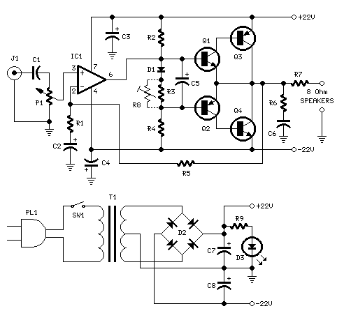
18W Audio Amplifier
Can be directly connected to CD players, tuners and tape recorders.
The circuit described above can be interfaced directly with various audio devices such as CD players, tuners, and tape recorders. This indicates that the circuit is designed to handle audio...
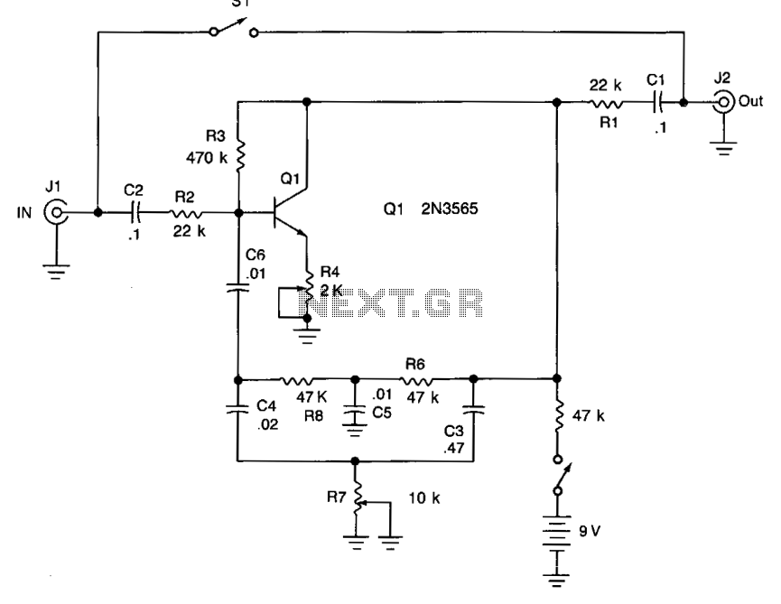
Funk box
Adjusting potentiometer R7 introduces additional tonal variation from low to high frequencies. To configure the unit, adjust potentiometer R4 until an oscillation or whistle is heard, then reduce R4 until the oscillation stops. The tonal effect can be modified from...
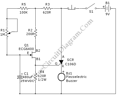
Long Period SCR Timer
This is an SCR timer circuit. In this circuit, an SCR is utilized to activate the final actuator, which is a buzzer. The time constant of the circuit is determined by resistor R1 and capacitor C1. The buzzer will sound...