


LX-800 Chaser & Strobe
#strobe
#chaser
#oscillator
#bass-beat extractor
#LED
#controller
#lighting
#stand-alone
#remote control
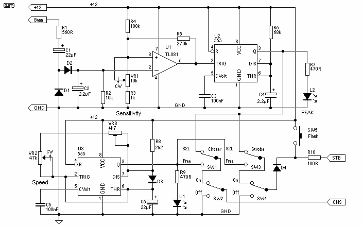
Description: The strobe controller is essentially a stand-alone device, even though it is part of the console PCB. It connects through a two-wire cable to the remote strobe head. Control, input source selection and output routing are on the console. The input to the strobe controller and/or chaser is either through a bass-beat extractor circuit or a free-running oscillator, both of which are shared by the chaser and the strobe controller.
The strobe controller functions as an integral component in lighting systems, particularly in theatrical and entertainment applications. Its design allows for seamless integration with a console PCB, ensuring that it can be operated remotely via a two-wire cable linked to the strobe head. The two-wire connection facilitates both power and control signals, allowing the strobe head to activate in sync with the audio or visual cues dictated by the console.
The operational control of the strobe controller is centralized on the console, where users can select input sources and manage output routing effectively. This centralized control enhances usability, enabling operators to adjust settings in real-time during performances. The input options for the strobe controller are versatile, accommodating either a bass-beat extractor circuit or a free-running oscillator. The bass-beat extractor is particularly useful in synchronizing the strobe effect with the rhythm of the music, creating a dynamic visual experience that enhances the overall ambiance of the performance. Conversely, the free-running oscillator provides a continuous strobe effect, independent of external audio, which can be employed for various artistic effects.
The shared use of the input circuits between the chaser and the strobe controller allows for a compact design, reducing the complexity and potential points of failure in the system. This feature also fosters flexibility in design, enabling the integration of additional features or modifications without extensive redesign of the existing circuitry.
In summary, the strobe controller is a pivotal element in lighting design, offering both reliability and versatility in theatrical applications. Its ability to connect directly to a console PCB and operate with various input sources makes it a valuable tool for lighting designers and operators alike.The strobe controller is essentially a stand-alone device, even though it is part of the console PCB. It connects through a two-wire cable to the remote strobe head. Control, input source selection and output routing are on the console. The input to the strobe controller and/or chaser is either through a bass-beat extractor circuit or a free-running oscillator, both of which are shared by the chaser and the strobe controller.
The chaser was developed out of an urgent need by one of the directors of a show I was involved in. It was designed, de-bugged and constructed in a single evening - because the director wouldn`t take no for an answer (show me a theatrical director wh
The strobe controller functions as an integral component in lighting systems, particularly in theatrical and entertainment applications. Its design allows for seamless integration with a console PCB, ensuring that it can be operated remotely via a two-wire cable linked to the strobe head. The two-wire connection facilitates both power and control signals, allowing the strobe head to activate in sync with the audio or visual cues dictated by the console.
The operational control of the strobe controller is centralized on the console, where users can select input sources and manage output routing effectively. This centralized control enhances usability, enabling operators to adjust settings in real-time during performances. The input options for the strobe controller are versatile, accommodating either a bass-beat extractor circuit or a free-running oscillator. The bass-beat extractor is particularly useful in synchronizing the strobe effect with the rhythm of the music, creating a dynamic visual experience that enhances the overall ambiance of the performance. Conversely, the free-running oscillator provides a continuous strobe effect, independent of external audio, which can be employed for various artistic effects.
The shared use of the input circuits between the chaser and the strobe controller allows for a compact design, reducing the complexity and potential points of failure in the system. This feature also fosters flexibility in design, enabling the integration of additional features or modifications without extensive redesign of the existing circuitry.
In summary, the strobe controller is a pivotal element in lighting design, offering both reliability and versatility in theatrical applications. Its ability to connect directly to a console PCB and operate with various input sources makes it a valuable tool for lighting designers and operators alike.The strobe controller is essentially a stand-alone device, even though it is part of the console PCB. It connects through a two-wire cable to the remote strobe head. Control, input source selection and output routing are on the console. The input to the strobe controller and/or chaser is either through a bass-beat extractor circuit or a free-running oscillator, both of which are shared by the chaser and the strobe controller.
The chaser was developed out of an urgent need by one of the directors of a show I was involved in. It was designed, de-bugged and constructed in a single evening - because the director wouldn`t take no for an answer (show me a theatrical director wh
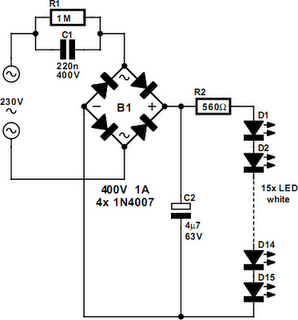
Mains Powered White LED Lamp
An array of white LEDs can serve as a compact lamp for living spaces. These LED lamps are commercially available and resemble standard halogen lamps, fitting into typical 230-V light fixtures. Upon inspection, it is evident that a capacitor is...
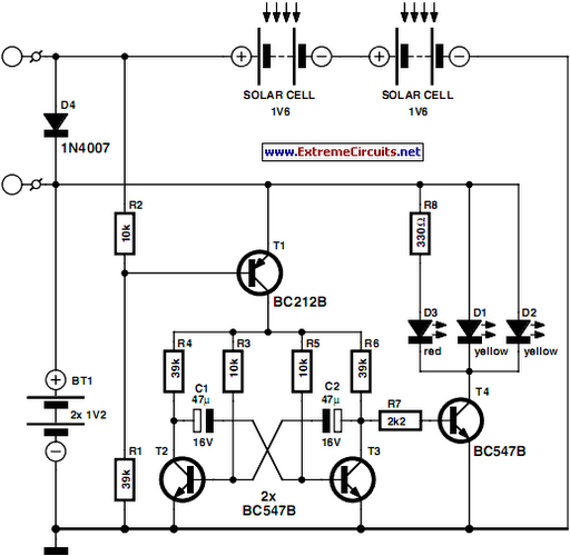
High-intensity LED Warning Flasher
This circuit is designed as a warning flasher to alert road users to dangerous situations in low-light conditions. It can also function as a bicycle light, adhering to traffic regulations. White LEDs are recommended for use as a front bicycle...
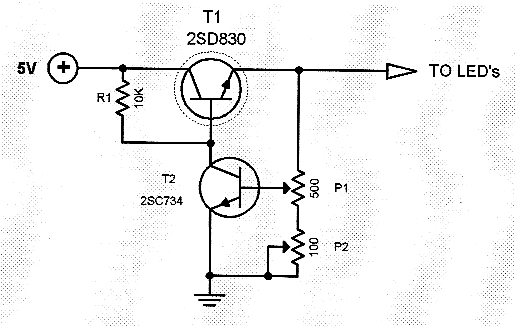
LED dimmer circuit
Typical segment display LEDs consume around 25 mA for each segment and should be limited to this current with resistors. For a six-digit display to be current limited, at least 42 series resistors are needed. The brightness of the LEDs...
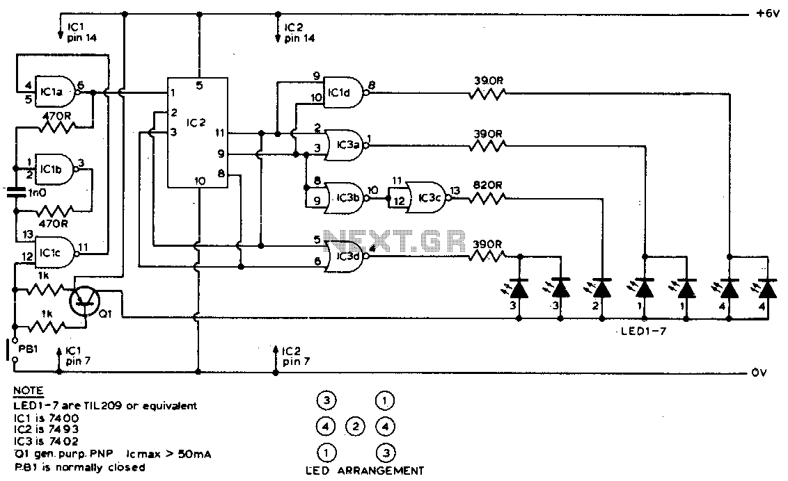
Electronic dice
Six LEDs are arranged to create a display that mimics the dots on a dice. When the push button input (PBI) is pressed, the display is turned off, and the oscillator (IC1 a, b, c) drives IC2 at approximately 1...
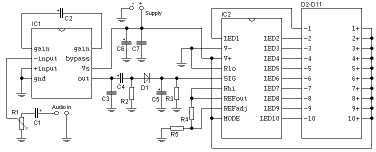
10 LED VU meter with LM3915
Supply voltage: 12 V. Supply current: 10 mA in stand-by, max. 80 mA. Input voltage: min. 20 mV rms. Indication range: 30 dB. LED currents: 7 mA. Ref. voltage of IC2: 5 V More: R1 - trimmer 100 k mini...
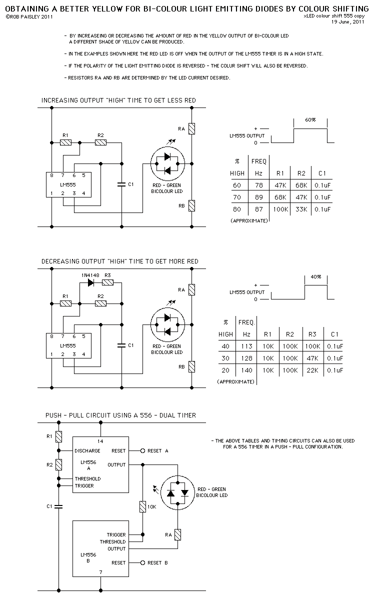
Colour Shifting LED`s
These circuits provide a means of altering the YELLOW output of RED / GREEN type two colour light emitting diodes. These circuits use the LM555 timer chip.
The circuit described utilizes the LM555 timer integrated circuit (IC) to modulate the output...
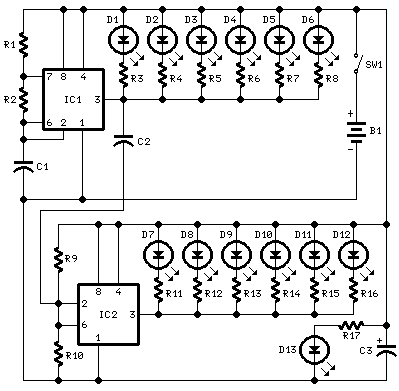
Bicycle back Safety Lights
This circuit is designed to provide a clearly visible light using 13 high-efficiency flashing LEDs arranged in a pseudo-rotating order. Due to its low voltage, low battery drain operation, and compact size, the device is suitable for mounting on bicycles...
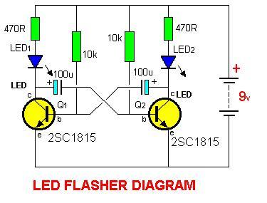
2SC1815 Flip Flop LED Flasher Suite
2SC1815 Flip Flop LED Flasher is a very simple and easy-to-understand circuit.
The 2SC1815 Flip Flop LED Flasher circuit utilizes a 2SC1815 transistor, which is a general-purpose NPN transistor, to create a basic LED flasher. This circuit operates on the principle...
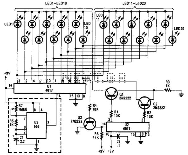
Light Chaser I
Up to 100 lights, LEDs, or optocoupler triac circuits can be sequentially activated by this circuit. One (U1) 4017 decodes and sequences 10 LEDs, whose common anode is returned through a second (U2) CD4017, which counts at one-tenth of the...