


Mains operated led Lamp
#LED
#mains
#230V
#fluorescent lamp adapter
#DIY
#home lighting
#energy efficient
#scrap parts
#electrical
#home improvement
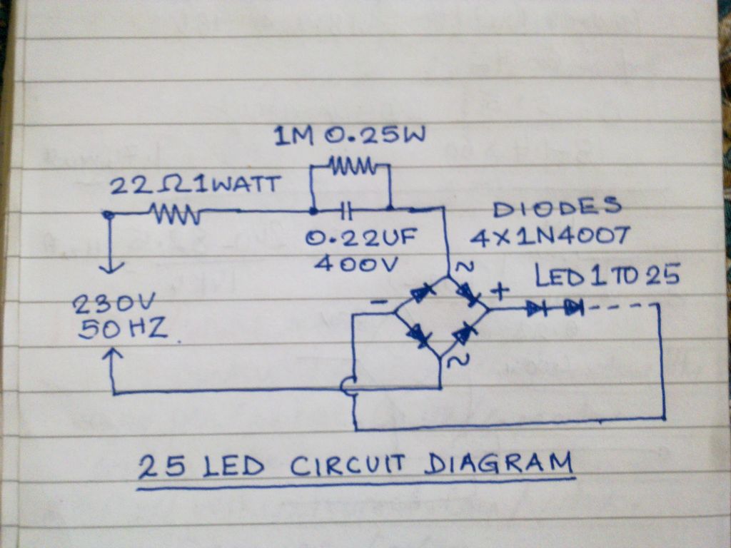
Description: This circuit operates 25 LEDs powered by a mains supply of 230V. A fluorescent lamp adapter was acquired from a scrap dealer for ease of disassembly.
The circuit consists of a series of 25 light-emitting diodes (LEDs) arranged to operate from a standard 230V AC mains supply. The use of a fluorescent lamp adapter serves as a key component in this design, as it allows for the conversion of high-voltage AC to a suitable voltage for the LEDs, which typically operate at low DC voltages.
To implement this circuit, the fluorescent lamp adapter must be modified to ensure safe and efficient operation. The first step involves disassembling the adapter to access its internal components. This usually includes a transformer that steps down the voltage, a rectifier to convert AC to DC, and possibly a driver circuit to regulate the current flowing to the LEDs.
Once the adapter is modified, it is essential to connect the LEDs in a configuration that allows for uniform brightness and distribution of light. This can be achieved by connecting the LEDs in parallel or series, depending on the voltage output of the modified adapter. If the adapter provides a higher voltage output, series connection is preferred, while parallel connection is suitable for lower voltage outputs.
Proper heat dissipation must also be considered, as LEDs can generate heat during operation. Adequate spacing and possibly the inclusion of heat sinks will help maintain optimal operating temperatures and prolong the lifespan of the LEDs.
Safety precautions should be taken when working with mains voltage. Insulation of all exposed connections and components is crucial to prevent electrical shock or short circuits. A fuse can also be integrated into the circuit for added protection against overload conditions.
In conclusion, this circuit design effectively utilizes a fluorescent lamp adapter to power 25 LEDs from a 230V mains supply, demonstrating a practical application of recycling electronic components while providing a reliable light source.Hi This is a 25 nos Led operated from mains of 230v supply. I bought a flourscent lamp adapter from a scrap dealer, because its easy to disman..
The circuit consists of a series of 25 light-emitting diodes (LEDs) arranged to operate from a standard 230V AC mains supply. The use of a fluorescent lamp adapter serves as a key component in this design, as it allows for the conversion of high-voltage AC to a suitable voltage for the LEDs, which typically operate at low DC voltages.
To implement this circuit, the fluorescent lamp adapter must be modified to ensure safe and efficient operation. The first step involves disassembling the adapter to access its internal components. This usually includes a transformer that steps down the voltage, a rectifier to convert AC to DC, and possibly a driver circuit to regulate the current flowing to the LEDs.
Once the adapter is modified, it is essential to connect the LEDs in a configuration that allows for uniform brightness and distribution of light. This can be achieved by connecting the LEDs in parallel or series, depending on the voltage output of the modified adapter. If the adapter provides a higher voltage output, series connection is preferred, while parallel connection is suitable for lower voltage outputs.
Proper heat dissipation must also be considered, as LEDs can generate heat during operation. Adequate spacing and possibly the inclusion of heat sinks will help maintain optimal operating temperatures and prolong the lifespan of the LEDs.
Safety precautions should be taken when working with mains voltage. Insulation of all exposed connections and components is crucial to prevent electrical shock or short circuits. A fuse can also be integrated into the circuit for added protection against overload conditions.
In conclusion, this circuit design effectively utilizes a fluorescent lamp adapter to power 25 LEDs from a 230V mains supply, demonstrating a practical application of recycling electronic components while providing a reliable light source.Hi This is a 25 nos Led operated from mains of 230v supply. I bought a flourscent lamp adapter from a scrap dealer, because its easy to disman..
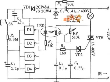
LED Lamp Dimmer Circuit Schematic Diagram
The diagram illustrates a lamp dimmer that gradually increases and decreases light intensity. This feature prevents sudden illumination, which can be a shock to the human eye, and also minimizes damage caused by inrush current when the lamp is turned...
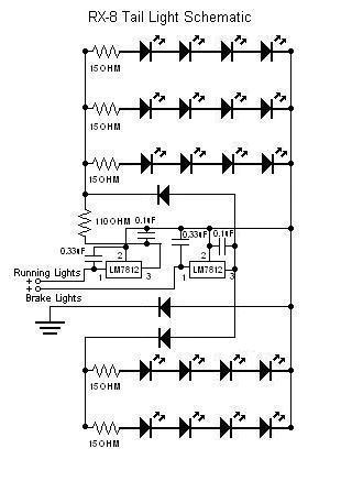
RX-8 LED
The circuit has been successfully recreated and functions properly when the line connected to the 1 µF capacitor of the "2" terminal of the running lights' LM7812 is not grounded. This line is also connected to the 33 µF capacitor...
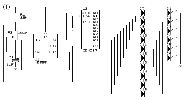
Knightrider lights for model cars
This simple circuit drives 6 LEDs in Knightrider scanner mode. Power consumption depends mainly on the type of LEDs used if you use a 7555 (555 CMOS version). More: Note that VDD and GND for the ICs are not shown...
Fake Alarming LED Flasher
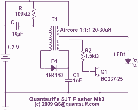
The parts to the right of T1 form a simple Joule-thief ('Blocking' oscillator) circuit which boosts the 1.2v supply to 3.5v to operate the LED. C1 is used to extend the charge and discharge cycles to increase brightness and efficiency....
Using LEDs as colour sensors
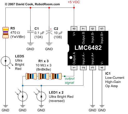
This circuit converts the analog signal from the reversed LED, which is in sensing mode, and amplified by the operational amplifier, into a digital (on/off) signal. The original complex design has been simplified. An alternative approach is discussed in a...
LED VU Meter by LM339 PCB
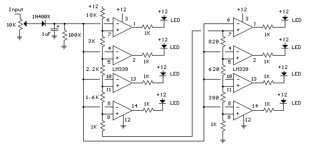
The circuit utilizes two quad voltage comparators (LM339) to illuminate a series of eight LEDs that indicate volume levels. Each of the eight comparators is set to specific bias voltages determined by a voltage divider, allowing the lower right LED...
White LED Flood Lamp circuit
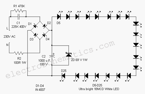
This white LED light illuminates the porch with cool white light. The circuit features a simple and energy-saving design. Its current consumption is practical.
The white LED light circuit is designed to provide efficient illumination while minimizing energy usage. The primary...
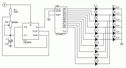
Knightrider lights for model cars
This simple circuit drives six LEDs in a "Knightrider scanner mode." Power consumption primarily depends on the type of LEDs used, especially if a 7555 (555 CMOS version) is utilized.
The circuit operates by sequentially illuminating the LEDs to create a...
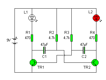
flashing lights
The flashing LED light circuit, known as an astable multivibrator, is illustrated in the accompanying circuit diagram. This circuit comprises two transistors (TR1 and TR2), two electrolytic capacitors (C1 and C2), two LEDs (L1 and L2), and four resistors (R1...