


Motion Sensor Switch for Light
#PIR module
#motion sensor
#relay
#12VDC
#solar power
#home automation
#security
#energy saving
#outdoor lighting
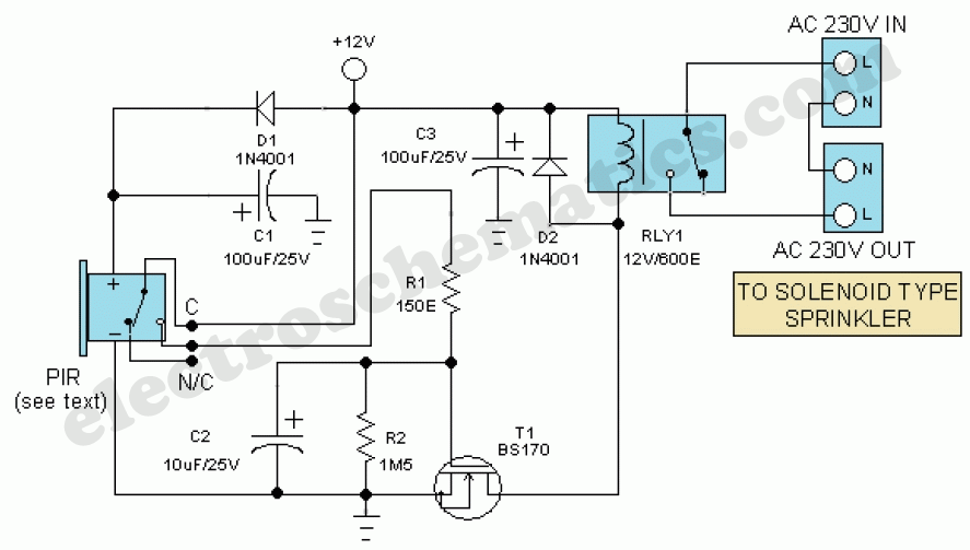
Description: Install the PIR module hanging from a 3-meter high mast to cover a 10-meter radius area. Connect its supply and relay terminals to the finished and enclosed circuit, ensuring the correct polarity is observed. A 4-core screened cable can be utilized for this interconnection. Power the circuit using a regulated 12V DC adapter or a solar power box. Whenever the PIR module detects movement of a live body, its relay output toggles, and the switching MOSFET (T1) in the circuit is activated via resistor R1 and associated components. Consequently, the electromagnetic relay at the output of T1 is engaged, allowing the electric sprinkler to receive power through the relay (RLY1) contacts. These contacts (or spare contacts) can also be employed to activate a high-power warning alarm. It is important to note that T1 is configured as a mini electronic timer. Even after the PIR relay is switched off, the output relay (RLY1) remains in the on state for a brief period determined by the value of the timing capacitor C2.
The described circuit integrates a Passive Infrared (PIR) sensor module, which is critical for detecting motion within a specified radius. The sensor is mounted at a height of 3 meters, optimizing its field of view to cover an area of approximately 10 meters in radius. The connection of the PIR module to the main circuit is facilitated through a 4-core screened cable, which minimizes interference and ensures stable communication between components.
Powering the circuit is achieved through a regulated 12V DC power supply, which can either be sourced from a conventional adapter or a solar power box, providing flexibility in installation locations. The PIR sensor's relay output is designed to toggle upon detecting movement, which triggers the MOSFET (T1) to activate. Resistor R1 serves as a current-limiting component, ensuring that T1 operates within safe parameters.
Upon activation of T1, the electromagnetic relay (RLY1) is energized, allowing current to flow to the electric sprinkler system. This relay serves as a control mechanism, enabling the sprinkler to operate only when movement is detected, thus conserving water and energy. The circuit design also incorporates spare contacts on RLY1, which can be utilized for additional functionalities, such as activating a high-power warning alarm, enhancing the system's overall utility.
T1 is configured as a mini electronic timer, which provides a delay feature. This means that even after the PIR sensor no longer detects motion and its relay output turns off, the output relay (RLY1) remains activated for a short duration. This delay is adjustable and is determined by the timing capacitor (C2), allowing customization of the system's response time to suit specific operational requirements. This feature can be particularly beneficial in applications where a sustained operation is necessary after initial activation, such as allowing the sprinkler to complete its cycle before shutting off.Install the PIR module hanging from a 3 metre high mast (to cover 10 metre radius area) and connect its supply and relay terminals to our finished and enclosed circuit, observing right polarity. A 4-core screened cable can be used for this interconnection. Power the circuit from a regulated 12VDC adaptor/solar power box. Whenever the PIR module detect movement of a live body its relay output toggles and the switching mosfet (T1) in the circuit is switched to on via resistor R1 and related parts. As as result, the EM relay at the output of T1 is activated and the electric sprinkler gets its supply through the relay (RLY1) contacts.
This contacts (or spare contacts) can also be used to activate a high-power warning alarm. Please note that, here T1 is wired as a mini electronic timer. Even after the PIR relay switched off, output relay (RLY1) remains in on state for a short duration decided by the value of timing capacitor C2.
The described circuit integrates a Passive Infrared (PIR) sensor module, which is critical for detecting motion within a specified radius. The sensor is mounted at a height of 3 meters, optimizing its field of view to cover an area of approximately 10 meters in radius. The connection of the PIR module to the main circuit is facilitated through a 4-core screened cable, which minimizes interference and ensures stable communication between components.
Powering the circuit is achieved through a regulated 12V DC power supply, which can either be sourced from a conventional adapter or a solar power box, providing flexibility in installation locations. The PIR sensor's relay output is designed to toggle upon detecting movement, which triggers the MOSFET (T1) to activate. Resistor R1 serves as a current-limiting component, ensuring that T1 operates within safe parameters.
Upon activation of T1, the electromagnetic relay (RLY1) is energized, allowing current to flow to the electric sprinkler system. This relay serves as a control mechanism, enabling the sprinkler to operate only when movement is detected, thus conserving water and energy. The circuit design also incorporates spare contacts on RLY1, which can be utilized for additional functionalities, such as activating a high-power warning alarm, enhancing the system's overall utility.
T1 is configured as a mini electronic timer, which provides a delay feature. This means that even after the PIR sensor no longer detects motion and its relay output turns off, the output relay (RLY1) remains activated for a short duration. This delay is adjustable and is determined by the timing capacitor (C2), allowing customization of the system's response time to suit specific operational requirements. This feature can be particularly beneficial in applications where a sustained operation is necessary after initial activation, such as allowing the sprinkler to complete its cycle before shutting off.Install the PIR module hanging from a 3 metre high mast (to cover 10 metre radius area) and connect its supply and relay terminals to our finished and enclosed circuit, observing right polarity. A 4-core screened cable can be used for this interconnection. Power the circuit from a regulated 12VDC adaptor/solar power box. Whenever the PIR module detect movement of a live body its relay output toggles and the switching mosfet (T1) in the circuit is switched to on via resistor R1 and related parts. As as result, the EM relay at the output of T1 is activated and the electric sprinkler gets its supply through the relay (RLY1) contacts.
This contacts (or spare contacts) can also be used to activate a high-power warning alarm. Please note that, here T1 is wired as a mini electronic timer. Even after the PIR relay switched off, output relay (RLY1) remains in on state for a short duration decided by the value of timing capacitor C2.
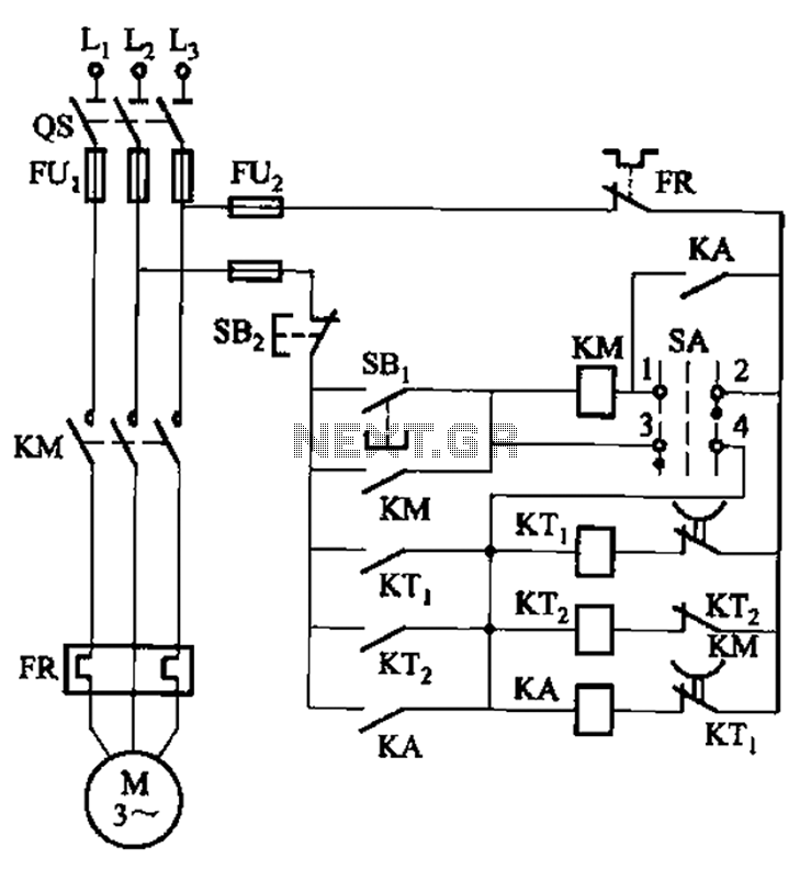
Third batch start and stop cycle control circuits
The circuit illustrated in Figure 3-78 utilizes two relays for automatic control, featuring a more complex line structure. This configuration allows for intermittent motor operation. Additionally, it can operate continuously when switch SA is positioned to the right.
The circuit employs...
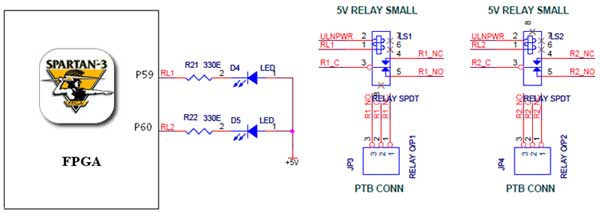
relay interfacing with spartan 3 primer
The Spartan-3 board features external 5V relay interfacing, as depicted in the accompanying figure. The ULN2803 is utilized as a driver for the FPGA I/O lines, with the driver outputs connected to the relay modules. A PTB connector is provided...
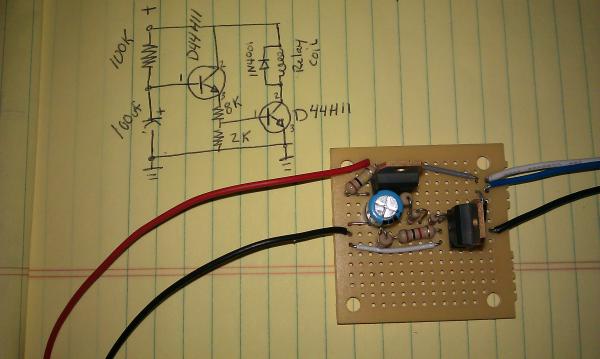
Homemade tablet CarPC
The momentary hold relay board and the accessory delay module are components designed for automotive applications. The momentary hold relay board powers the GPS unit and the tablet, eliminating the need for manual button activation. The accessory delay module is...
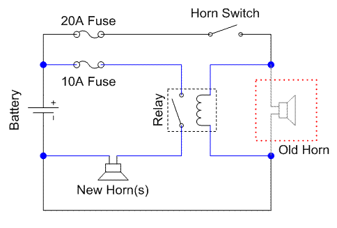
GS500 Horn
A relay is an electrically operated switch that utilizes a coil to create magnetism, which closes the contacts of the switch. In automotive applications, a 12V signal through the coil allows 12V to flow through the switch contacts. The advantage...
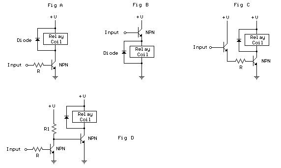
Logic level relay controller
The schematic below illustrates 4 methods of controlling a relay with a digital logic signal. Figure (A) can probably be used in most cases where the relay coil requires 100 mA or less and the input current is 2 milliamps...
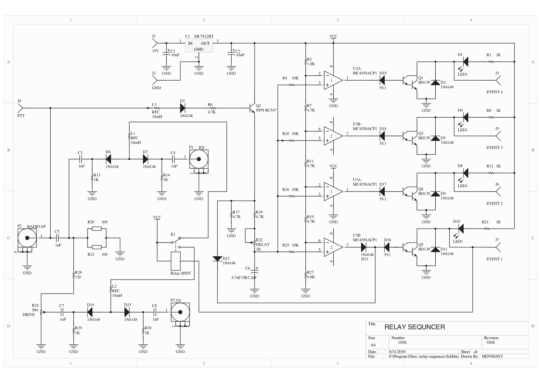
Relay Sequencer Board
A relay sequencer is utilized in a radio transverter to activate specific stages sequentially after a brief delay. This project outlines the construction of this sequencer, which features a stage that switches the output/input of the driving radio to the...
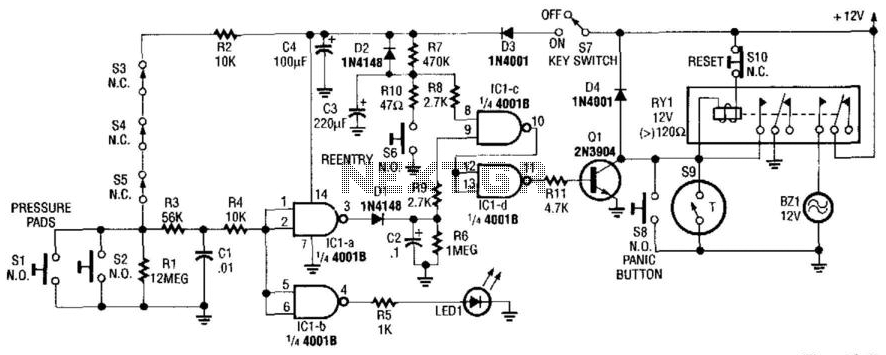
Home Security System
This alarm circuit activates when switches S1 through S5 are engaged. This action illuminates LED1 and triggers transistor Q1 through integrated circuits IC1C and IC1D. Relay RY1 is configured for self-latching. Switch S10 is utilized for resetting the circuit. When...

solar watering system
A solar-powered watering system has been proposed to irrigate plants daily using water collected in butts located by the greenhouse. This project has been under development for a considerable time and is now being revisited with the aim of completion....
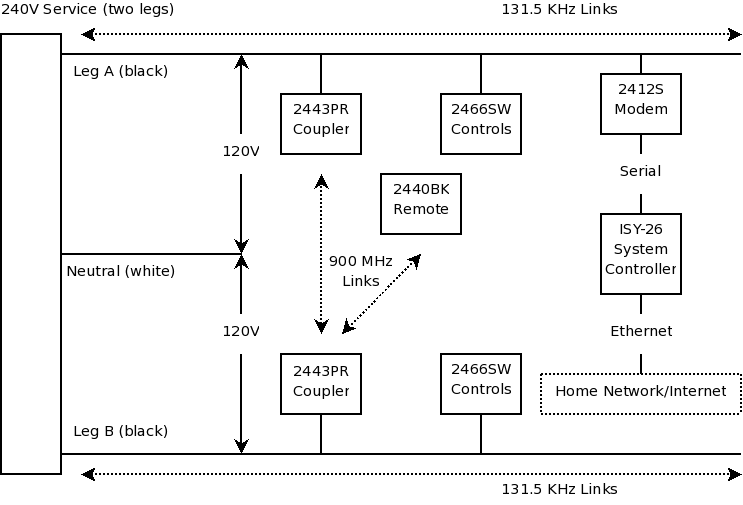
home automation Installation
First and foremost, if one is not skilled with tools and electrical systems, it is advisable to hire a qualified electrician rather than attempting to undertake this task independently. The electrician should review this page for specific cautions and advice....