


MS51C61 holiday lights ASIC circuit
#holiday lights
#ASIC
#220V AC
#bridge rectifier
#voltage supply
#LED
#lighting control
#rectifier circuit
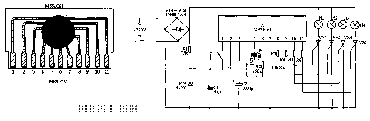
Description: The circuit utilizes a 220V AC input, which is converted to DC using a VD1-VD4 bridge rectifier. This rectified voltage is used to power four lights (H1 to H4). The circuit also includes a resistor (R1) for voltage limiting and a diode (VD5) for voltage regulation. Additionally, a capacitor (C1) acts as a filter for the power supply. A manual switch (SB) allows users to change the lighting mode, enabling a circular flashing effect with each press.
The described circuit begins with a 220V AC input, which is processed through a bridge rectifier composed of diodes VD1 to VD4. This configuration effectively converts the alternating current (AC) into direct current (DC), which is required for the operation of the subsequent components. The rectified output is then used to energize four separate lights labeled H1 through H4, providing illumination.
To ensure safe operation and to limit the voltage supplied to the lights, a resistor (R1) is incorporated into the circuit. This resistor serves the dual purpose of limiting current and preventing potential damage to the lights from excessive voltage. Following the resistor, diode VD5 functions as a voltage regulator, providing a stable output voltage to the circuit, thereby enhancing reliability and performance.
In addition to the basic lighting functionality, the circuit includes a filter capacitor (C1) connected to the power supply. This capacitor smooths out any voltage fluctuations resulting from the rectification process, ensuring a steady DC output. The presence of C1 is crucial for maintaining the performance of the lights, particularly in applications where consistent brightness is necessary.
Furthermore, the circuit is equipped with a manual switch (SB) that allows users to control the lighting mode. Each press of the switch alters the operation of the lights, enabling a circular flashing mode. This feature adds versatility to the circuit, making it suitable for various applications where dynamic lighting effects are desired.
Overall, this circuit design combines essential components to create a functional and adaptable lighting system, capable of providing both steady illumination and dynamic effects based on user input.220V AC by VD1-VD4 bridge rectifier, all the way to supply four lights HI ~ H4 electricity, another pass down Rl pressure limiting, VD5 voltage supply manifold A filter CI with electricity. SB for the manual key switch, each press can be changed becomes a circular lights flashing mode.
The described circuit begins with a 220V AC input, which is processed through a bridge rectifier composed of diodes VD1 to VD4. This configuration effectively converts the alternating current (AC) into direct current (DC), which is required for the operation of the subsequent components. The rectified output is then used to energize four separate lights labeled H1 through H4, providing illumination.
To ensure safe operation and to limit the voltage supplied to the lights, a resistor (R1) is incorporated into the circuit. This resistor serves the dual purpose of limiting current and preventing potential damage to the lights from excessive voltage. Following the resistor, diode VD5 functions as a voltage regulator, providing a stable output voltage to the circuit, thereby enhancing reliability and performance.
In addition to the basic lighting functionality, the circuit includes a filter capacitor (C1) connected to the power supply. This capacitor smooths out any voltage fluctuations resulting from the rectification process, ensuring a steady DC output. The presence of C1 is crucial for maintaining the performance of the lights, particularly in applications where consistent brightness is necessary.
Furthermore, the circuit is equipped with a manual switch (SB) that allows users to control the lighting mode. Each press of the switch alters the operation of the lights, enabling a circular flashing mode. This feature adds versatility to the circuit, making it suitable for various applications where dynamic lighting effects are desired.
Overall, this circuit design combines essential components to create a functional and adaptable lighting system, capable of providing both steady illumination and dynamic effects based on user input.220V AC by VD1-VD4 bridge rectifier, all the way to supply four lights HI ~ H4 electricity, another pass down Rl pressure limiting, VD5 voltage supply manifold A filter CI with electricity. SB for the manual key switch, each press can be changed becomes a circular lights flashing mode.
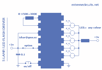
LED Flash Driver with HT2050
This circuit is based around HT2050 manufactured by HOLTEK semiconductors. It is a low cost, low-power C-MOS LSI designed for lamp and LED flash driver. It requires minimum external components. You can operate it with just two AAA cells or...
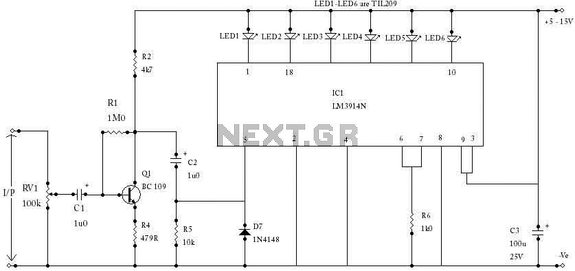
LED VU Meter with LM3914N
The circuit is based on an LM3914N bar graph display driver device (IC1), which can be used to drive up to ten LEDs. This is connected so that with OV12 at the input only the first LED indicator switches on....
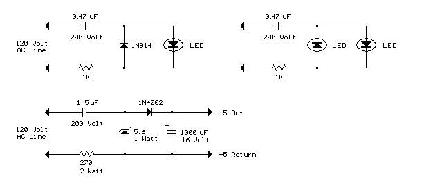
ac line powered leds
The circuit shown demonstrates how to power one or two LEDs from a 120-volt AC line by utilizing a capacitor to reduce the voltage and a small resistor to limit the inrush current. Because the capacitor needs to conduct current...
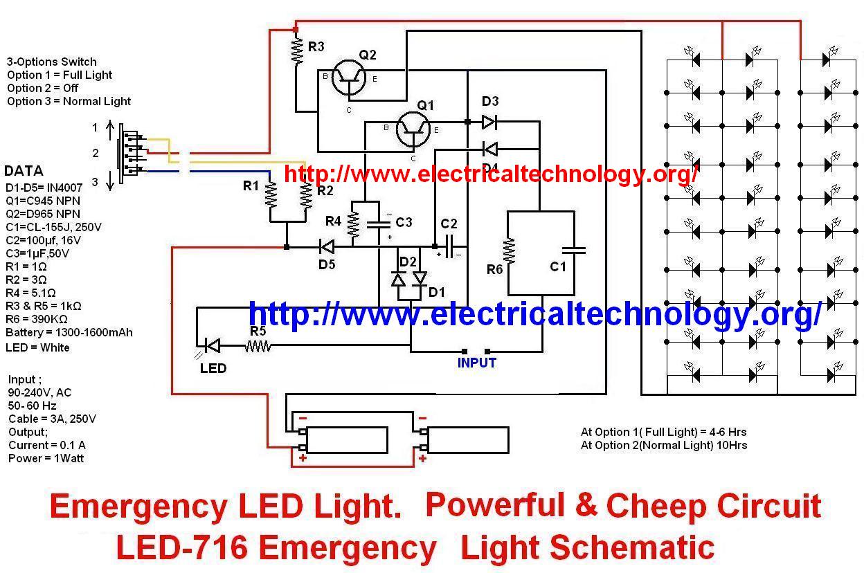
Emergency LED Light LED-716 Emergency Light Schematic
This circuit illustrates the modifications made due to a blown resistor on the backside, which was soldered in place. The issue was traced back to this specific resistor. Currently, the pattern change switch is set to Option 3, which corresponds...
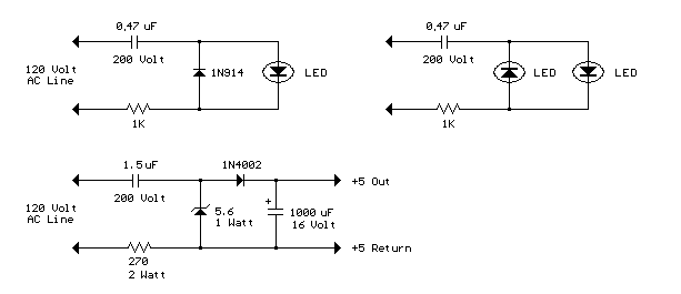
Power LEDs from Mains
The circuit below illustrates powering a LED (or two) from the 120 volt AC line using a capacitor to drop the voltage and a small resistor to limit the inrush current. Since the capacitor must pass current in both directions,...
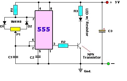
LED dimmer circuit
A user is new to the forum and has limited experience in DIY electronics. The current project involves creating a battery-powered LED dimmer circuit.
The objective of the project is to design a battery-operated LED dimmer circuit that allows for adjustable...
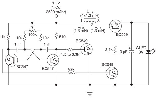
Pocket white-LED torch is power efficient
This single white LED torch can be housed in an empty glue stick tube and has a long rechargeable battery life.
The proposed circuit design features a compact LED torch that utilizes a single white LED as the primary light source....
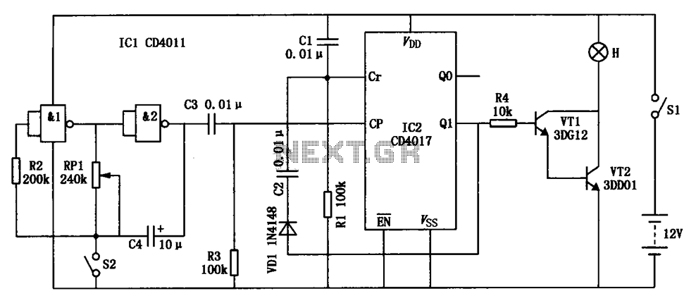
Construction LED circuit diagram CD4017 CD4011
The construction LED circuit illustrated in the figure requires manual power. Once powered, the light will blink to alert individuals to pay attention to safety.
The circuit is designed to enhance safety awareness in construction environments by utilizing a blinking LED...

Aquarium Led Lighting Circuit
This colorful backlit aquarium light provides a natural appearance to the aquarium tank. The aquarium LED lighting circuit automatically turns on at sunset.
The aquarium LED lighting system enhances the aesthetic appeal of the aquarium by simulating natural lighting conditions. The...