


Night circuit diagram showing target
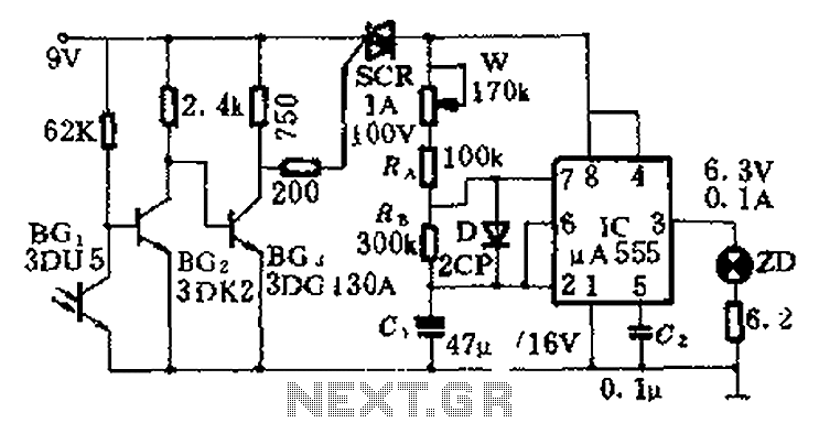
Description: This circuit is designed for nighttime illumination and corridor lighting. During daylight, sufficient light causes BG3 to conduct, preventing the SCR from oscillating. As a result, the circuit remains inactive, and the light does not turn on. At night, BG3 turns off, allowing the SCR to trigger and activate the oscillation circuit, which is composed of an integrated circuit (IC) among other components. The IC generates a continuous ultra-low frequency square wave output, with a frequency defined by the formula f = 1/T = 1.44/(W + Ra + 2Rb)C. The IC connects to an LED that produces a twinkling effect, making it visually striking. The values of Ra, Rb, and C1 can be adjusted to modify the flash frequency.
This circuit operates based on the principles of light detection and SCR (Silicon Controlled Rectifier) triggering. The BG3 component functions as a light sensor, effectively distinguishing between day and night conditions. During daylight hours, the ambient light level is sufficient to keep the BG3 in a conductive state, which prevents the SCR from entering its conductive phase. This ensures that the connected lighting remains off during the day, conserving energy and preventing unnecessary illumination.
Upon the onset of darkness, the BG3 sensor ceases to conduct, which allows the SCR to be triggered. The SCR is a critical component in this circuit, as it enables the flow of current through the oscillation circuit. The oscillation circuit is primarily driven by an integrated circuit (IC) that generates a square wave output. The frequency of this output is determined by the resistors (Ra, Rb) and the capacitor (C) in the circuit. The relationship between these elements is given by the formula f = 1/T = 1.44/(W + Ra + 2Rb)C, where W represents any additional components that may influence the timing characteristics.
The output of the IC is connected to an LED, which produces a twinkling light effect. This effect is visually appealing and serves to enhance the aesthetic of the corridor or area being illuminated. The flash frequency can be adjusted by varying the values of the resistors and capacitor, allowing for customization based on specific requirements or preferences.
Overall, this circuit effectively combines light sensing, SCR triggering, and oscillation generation to provide an energy-efficient and visually engaging lighting solution for nighttime applications. The use of adjustable components allows for flexibility in design, making it suitable for various environments and user needs. As shown, this circuit is suitable for shooting at night and turned on the lights corridor. During the day due to sufficient light, BG3 conduction, SCR blocking oscillation cir cuit by an IC or the like can not work without voltage, so light is not on. Night, since BG3 off, SCR triggered by conduction, so by the oscillation start oscillation circuit composed of IC, etc., IC 3 ultra-low frequency square wave output continuously, the frequency f 1/T 1.44/(W + Ra + 2Rb ) C, the IC can be seen between 3 and connected to the LED twinkling light, very eye-catching. Ra Rb as C1 adjust the size of flash frequency can be changed.
This circuit operates based on the principles of light detection and SCR (Silicon Controlled Rectifier) triggering. The BG3 component functions as a light sensor, effectively distinguishing between day and night conditions. During daylight hours, the ambient light level is sufficient to keep the BG3 in a conductive state, which prevents the SCR from entering its conductive phase. This ensures that the connected lighting remains off during the day, conserving energy and preventing unnecessary illumination.
Upon the onset of darkness, the BG3 sensor ceases to conduct, which allows the SCR to be triggered. The SCR is a critical component in this circuit, as it enables the flow of current through the oscillation circuit. The oscillation circuit is primarily driven by an integrated circuit (IC) that generates a square wave output. The frequency of this output is determined by the resistors (Ra, Rb) and the capacitor (C) in the circuit. The relationship between these elements is given by the formula f = 1/T = 1.44/(W + Ra + 2Rb)C, where W represents any additional components that may influence the timing characteristics.
The output of the IC is connected to an LED, which produces a twinkling light effect. This effect is visually appealing and serves to enhance the aesthetic of the corridor or area being illuminated. The flash frequency can be adjusted by varying the values of the resistors and capacitor, allowing for customization based on specific requirements or preferences.
Overall, this circuit effectively combines light sensing, SCR triggering, and oscillation generation to provide an energy-efficient and visually engaging lighting solution for nighttime applications. The use of adjustable components allows for flexibility in design, making it suitable for various environments and user needs. As shown, this circuit is suitable for shooting at night and turned on the lights corridor. During the day due to sufficient light, BG3 conduction, SCR blocking oscillation cir cuit by an IC or the like can not work without voltage, so light is not on. Night, since BG3 off, SCR triggered by conduction, so by the oscillation start oscillation circuit composed of IC, etc., IC 3 ultra-low frequency square wave output continuously, the frequency f 1/T 1.44/(W + Ra + 2Rb ) C, the IC can be seen between 3 and connected to the LED twinkling light, very eye-catching. Ra Rb as C1 adjust the size of flash frequency can be changed.

Light control relay control lamp
The circuit operates on 220V AC input, which is transformed to approximately 12V DC using a step-down transformer (T), a diode bridge rectifier (VDI-VD4), and a filter capacitor (C1). This setup is designed to power the entire circuit. The light...
Very Simple Radio Control (R/C)
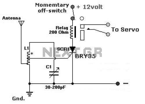
The diagram illustrates a simple and efficient receiver designed for controlling garage doors, starter motors, alarms, warning systems, and various other applications. The SCR utilized in this circuit features an exceptionally low trigger current of 30 µA.
The circuit operates as...
Simple Metal Detector
The diagram illustrates a simple and efficient receiver designed for activating garage doors, starter motors, alarms, warning systems, and various other applications. The SCR utilized in this circuit features an extremely low trigger current of 30 µA, requiring only 30...

Line-synchronized-driver
The gate drive that phase controls the four parallel SCRs is achieved using a complementary MOS hex gate MC14572 and two bipolar transistors. This adjustable line-synchronized driver allows SCR conduction from near zero to 180 degrees. A Schmitt trigger clocks...
High-torque motor speed control
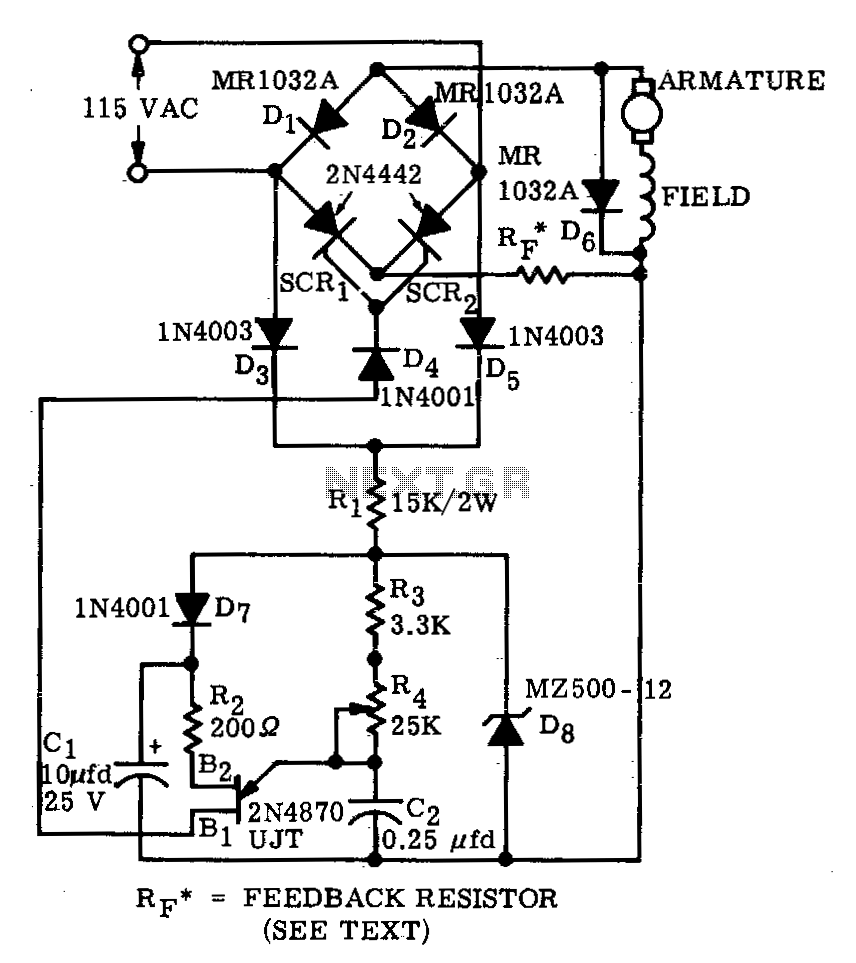
A bridge circuit consisting of two silicon-controlled rectifiers (SCRs) and two silicon rectifiers provides full-wave power to the motor. Diodes D3 and D5 deliver direct current (DC) to the trigger circuit through dropping resistors, R1. The phase delay of SCR...
Light control relay control lamp
The circuit operates on 220V AC input, which is transformed to approximately 12V DC using a step-down transformer (T), a diode bridge rectifier (VDI-VD4), and a filter capacitor (C1). This setup is designed to power the entire circuit. The light...

SCR relaxation flasher
Flashing occurs each time the capacitor discharges through the turned-on SCR. When the discharge current falls below the SCR holding current, the SCR turns off, and the capacitor begins charging for another cycle. The circuit will maintain a slower but...
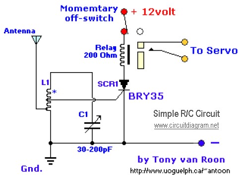
simple rc circuit
The diagram illustrates a straightforward and efficient receiver designed for activating garage doors, starter motors, alarms, warning systems, and various other applications. The silicon-controlled rectifier (SCR) utilized in this circuit features an exceptionally low trigger current of 30 µA, requiring...
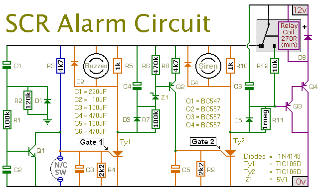
An SCR Based Burglar Alarm
This is a simple SCR-based burglar alarm circuit. Its features include automatic exit and entry delays, along with a timed bell cut-off and reset. It is designed to be used with the usual types of normally-closed input devices such as...