


Night Rider 16 Stage Bi-Directional LED Sequencer circuit
#LED sequencer
#CD4516
#74HC138
#Schmitt Trigger
#oscillator
#bi-directional
#counter
#decoder
#Night Rider
#adjustable rate
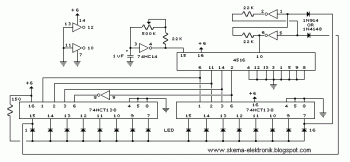
Description: The bi-directional sequencer utilizes a 4-bit binary up/down counter (CD4516) and two "1 of 8 line decoders" (74HC138 or 74HCT138) to create the well-known "Night Rider" display. A Schmitt Trigger oscillator generates the clock signal for the counter, with the rate adjustable via a 500K potentiometer. Additionally, two Schmitt Trigger inverters function as a Set/Reset latch to govern the counting direction (up or down). It is important to use the 74HC14 instead of the 74HCT14, as the latter may not operate correctly due to its lower TTL input trigger level. When the maximum count is reached (1111), the low output at pin 7 sets the latch, causing the UP/DOWN input to the counter to go low and prompting the counter to decrement. Conversely, when the minimum count is reached (0000), the latch is reset (high), allowing the counter to increment on the next rising clock edge. The three lowest counter bits (Q0, Q1, Q2) are connected in parallel to both decoders, while the highest bit (Q3) selects the appropriate decoder.
The bi-directional sequencer circuit is designed to produce a visually engaging "Night Rider" effect through the use of a 4-bit binary up/down counter (CD4516) that counts in both directions based on the input from an external control mechanism. The CD4516 counter is a versatile device that allows for both counting up and down, making it suitable for applications requiring reversible counting sequences.
The circuit employs two 1 of 8 line decoders (74HC138 or 74HCT138) to decode the binary output from the counter into a specific output line, illuminating LEDs in a sequential manner that mimics the original "Knight Rider" light pattern. The choice between the 74HC138 and 74HCT138 is critical; the 74HC14 Schmitt Trigger inverter is preferred for its higher input threshold levels, ensuring reliable operation in TTL logic environments.
A Schmitt Trigger oscillator is integrated to provide a stable clock signal for the counter, with its frequency adjustable via a 500K potentiometer. This adjustability allows for customization of the speed at which the display animates, providing flexibility for different applications.
The circuit also includes a Set/Reset latch implemented with two Schmitt Trigger inverters. This latch controls the direction of counting by determining whether the counter should increment or decrement. When the counter reaches its maximum count of 1111, the output at pin 7 goes low, setting the latch and switching the counting direction to decrement. Conversely, when the counter reaches its minimum count of 0000, the latch resets, enabling the counter to increment on the next clock pulse.
The output from the counter is structured so that the three least significant bits (Q0, Q1, Q2) are connected to both decoders in parallel, facilitating simultaneous decoding. The most significant bit (Q3) serves as a selector, determining which decoder is active based on the current count. This configuration ensures that the LEDs light up in a sequential pattern, enhancing the visual effect of the display. Overall, this circuit design offers a robust solution for creating dynamic lighting effects in various electronic projects.The bi-directional sequencer uses a 4 bit binary up/down counter (CD4516) and two "1 of 8 line decoders" (74HC138 or 74HCT138) to generate the popular "Night Rider" display. A Schmitt Trigger oscillator provides the clock signal for the counter and the rate can be adjusted with the 500K pot.
Two additional Schmitt Trigger inverters are used as a S ET/RESET latch to control the counting direction (up or down). Be sure to use the 74HC14 and not the 74HCT14, the 74HCT14 may not work due to the low TTL input trigger level. When the highest count is reached (1111) the low output at pin 7 sets the latch so that the UP/DOWN input to the counter goes low and causes the counter to begin decrementing.
When the lowest count is reached (0000) the latch is reset (high) so that the counter will begin incrementing on the next rising clock edge. The three lowest counter bits (Q0, Q1, Q2) are connected to both decoders in parallel and the highest bit Q3 is used to select the appropriate decoder.
The bi-directional sequencer circuit is designed to produce a visually engaging "Night Rider" effect through the use of a 4-bit binary up/down counter (CD4516) that counts in both directions based on the input from an external control mechanism. The CD4516 counter is a versatile device that allows for both counting up and down, making it suitable for applications requiring reversible counting sequences.
The circuit employs two 1 of 8 line decoders (74HC138 or 74HCT138) to decode the binary output from the counter into a specific output line, illuminating LEDs in a sequential manner that mimics the original "Knight Rider" light pattern. The choice between the 74HC138 and 74HCT138 is critical; the 74HC14 Schmitt Trigger inverter is preferred for its higher input threshold levels, ensuring reliable operation in TTL logic environments.
A Schmitt Trigger oscillator is integrated to provide a stable clock signal for the counter, with its frequency adjustable via a 500K potentiometer. This adjustability allows for customization of the speed at which the display animates, providing flexibility for different applications.
The circuit also includes a Set/Reset latch implemented with two Schmitt Trigger inverters. This latch controls the direction of counting by determining whether the counter should increment or decrement. When the counter reaches its maximum count of 1111, the output at pin 7 goes low, setting the latch and switching the counting direction to decrement. Conversely, when the counter reaches its minimum count of 0000, the latch resets, enabling the counter to increment on the next clock pulse.
The output from the counter is structured so that the three least significant bits (Q0, Q1, Q2) are connected to both decoders in parallel, facilitating simultaneous decoding. The most significant bit (Q3) serves as a selector, determining which decoder is active based on the current count. This configuration ensures that the LEDs light up in a sequential pattern, enhancing the visual effect of the display. Overall, this circuit design offers a robust solution for creating dynamic lighting effects in various electronic projects.The bi-directional sequencer uses a 4 bit binary up/down counter (CD4516) and two "1 of 8 line decoders" (74HC138 or 74HCT138) to generate the popular "Night Rider" display. A Schmitt Trigger oscillator provides the clock signal for the counter and the rate can be adjusted with the 500K pot.
Two additional Schmitt Trigger inverters are used as a S ET/RESET latch to control the counting direction (up or down). Be sure to use the 74HC14 and not the 74HCT14, the 74HCT14 may not work due to the low TTL input trigger level. When the highest count is reached (1111) the low output at pin 7 sets the latch so that the UP/DOWN input to the counter goes low and causes the counter to begin decrementing.
When the lowest count is reached (0000) the latch is reset (high) so that the counter will begin incrementing on the next rising clock edge. The three lowest counter bits (Q0, Q1, Q2) are connected to both decoders in parallel and the highest bit Q3 is used to select the appropriate decoder.
decoder
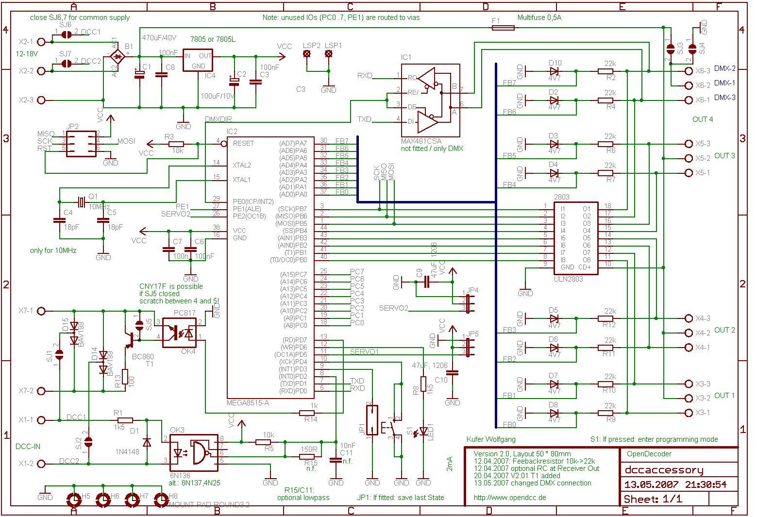
There is a version without SMD, referred to as version 2.1, which is slightly larger (80 x 100 mm) and features dual drivers capable of handling a 1A load. It operates using the same software. The input voltage from the...
Schmitt Trigger VU Meter
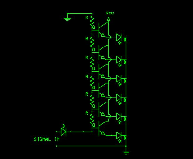
The schematic indicates that the input is routed through a voltage divider. This configuration is essential for the operation of the Schmitt triggers, which all activate under certain conditions.
The voltage divider in the schematic serves to scale down the input...
Electronic pests killing lamp circuit diagram 4
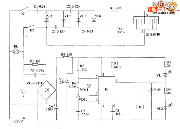
The electronic pest-killing lamp circuit comprises an oscillator, control circuit, high voltage generator, LED indicator circuit, and power supply circuit. The schematic diagram illustrates these components. The oscillator circuit includes a time-base integrated circuit (IC), resistors R5 to R7, diodes...
Vhf-modulator
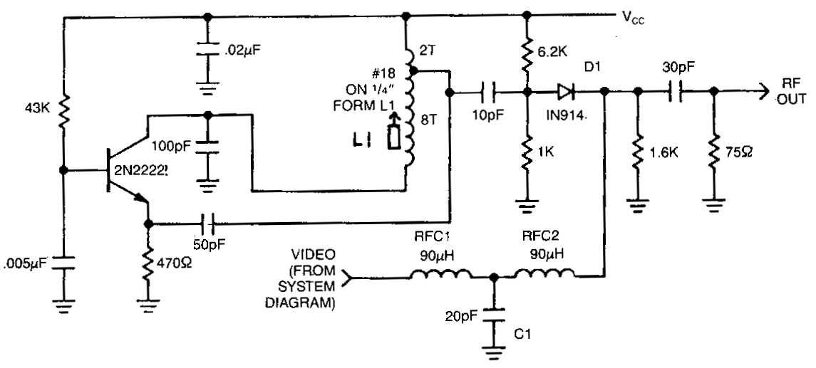
This circuit utilizes an oscillator (2N2222) and a diode (D1) as a nonlinear mixer. The frequency is determined by a slug in L1. RFCl, C1, and RFC2 create a low-pass filter designed to pass video signals while blocking RF signals...
Wide frequency oscillator
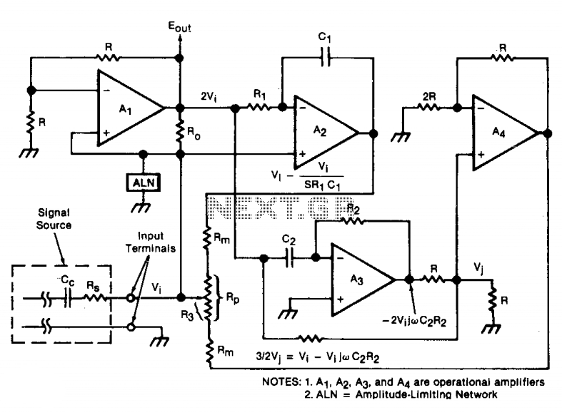
An oscillator/amplifier is resistively tunable over a wide frequency range. Feedback circuits containing operational amplifiers, resistors, and capacitors synthesize the electrical effects of inductance and capacitance in parallel between the input terminals. The synthetic inductance and capacitance, and therefore the...
Three light control road construction warning light circuit
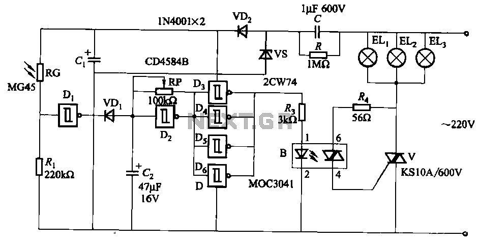
The circuit utilizes a CD4584B six Schmitt trigger integrated circuit (IC) with components Di and Ri forming a photometric circuit. D2, along with RP and C2, comprises an adjustable frequency ultra-low frequency oscillation device, where RP serves as an adjustment...
5 Volt to 12 Volt bi-directional lamp sequencer
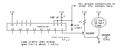
The circuit below is designed to be used with the bi-directional lamp sequencer shown above on this same page. Two additional transistors are used to increase the current from the 74HCT138 decoder to control 12 volt 25 watt lamps. A...
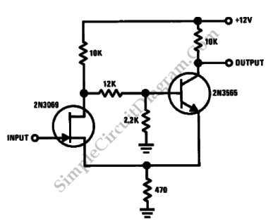
Discrete Schmitt Trigger
This is a Schmitt trigger circuit. This circuit produces a simple comparator action. It is emitter-coupled. This circuit has a distinct hysteresis loop.
The Schmitt trigger circuit is a fundamental electronic component utilized for signal conditioning, providing a means to convert...
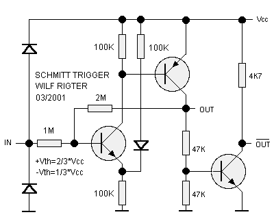
Schmitt Inverter
The Schmitt trigger is a specialized circuit that functions as a switch, altering its state at two distinct voltage thresholds known as the upper and lower thresholds, or the positive and negative-going thresholds. The difference between these two threshold levels...