


Norman P2000D Modeling Light Circuitry
#modeling light
#independent circuit
#on/off switch
#strobe
#photography
#light control
#dual channel
#electronics
#circuit design
#power management

Description: There are two independent modeling light circuits for the P2000D, one for each of the two channels. The modeling light circuit is completely separate from the high voltage strobe circuitry, even featuring its own On/Off switch. Therefore, the functionality of the modeling lights does not indicate the operational status of the strobe circuits. Caution is advised when purchasing a unit that claims the modeling lights are functional while the strobe has not been tested. On the top panel, there are two potentiometers for adjusting the modeling light power levels, which connect to a small circuit board located in the upper section of the pack. This circuit board utilizes a TRIAC dimmer to regulate the intensity of the lamps. The output from this board is transmitted via a grey wire to Pin F on the strobe lamp connectors, with return power routed through Pin E. The schematic of the control board was traced out to the best of the ability, though the value of the trim pot was not measured, and the DIAC could not be identified, although it is presumed to be a DIAC based on similar dimmer schematics. A basic layout and circuit traces were sketched for potential future repairs. Initially, there was no strobe head available, but a Norman TriLite, which functions as both a projector lamp and strobe light in a spotlight assembly, was later acquired. With a foundational understanding of the modeling light circuit established, attention will now shift to sketching the high voltage circuitry used for the strobes. The absence of a sufficiently large transformer for stepping up mains voltage suggests that a voltage multiplier is employed; a 2X multiplier would be inadequate, while a 3X multiplier is anticipated to be sufficient.
The P2000D features dual independent modeling light circuits, each corresponding to its respective channel. This design allows for versatile lighting control without interference from the strobe circuitry, which operates at high voltage. Each modeling light circuit includes an On/Off switch, ensuring that users can operate the modeling lights independently of the strobe functionality, which is critical for troubleshooting and maintenance.
The top panel of the P2000D contains two potentiometers that allow for precise adjustment of the modeling light power levels. These potentiometers are connected to a dedicated circuit board located within the upper section of the device. This circuit board employs a TRIAC dimmer, which is a solid-state device known for its ability to control power flow and adjust the brightness of incandescent lamps. The TRIAC is controlled by the potentiometers, enabling smooth dimming of the modeling lights.
The output from the TRIAC dimmer is routed through a grey wire to Pin F on the strobe lamp connectors, while the return path for power is established via Pin E. This configuration ensures that the modeling lights receive the appropriate voltage and current levels for optimal performance. The schematic for the control board has been carefully traced to facilitate any necessary repairs in the future, although specific component values, such as the trim pot, were not documented.
As the project progressed, the acquisition of a Norman TriLite provided an opportunity to further explore the high voltage circuitry associated with the strobe operation. The absence of a transformer capable of stepping up the mains voltage indicates that a voltage multiplier is likely in use. A 3X voltage multiplier would provide the necessary voltage levels for strobe operation, as a 2X multiplier would fall short of the required specifications. This understanding of both the modeling light and strobe circuits is essential for effective troubleshooting and repair of the P2000D lighting system.There are two independent modeling light circuits for the P2000D - one for each of the two channels. The modeling light circuit is completely independent from the high voltage strobe circuitry - to the point of having its own On/Off switch. This means, of course, that just because the modeling lights are working your strobe circuits can be fried.
Be careful if someone sells you a pack and says - well I can`t test the strobe but the modeling lights are working. There are two modeling light power level potientiometers on the top panel. These lead to a small circuit board in the top half of the pack. This circuit board uses a fairly simple TRIAC dimmer to control the intensity of the lamps. The output from this board runs via a grey wire to Pin F on the strobe lamp connectors. Return power goes via pin E. I traced out the schematic of the control board as best I could. I did not attempt to measure the value of trim pot and could not identify the DIAC (though I pretty much am sure that it is a DIAC based on other dimmer schematics.
) I then sketched out the basic layout and circuit traces in case I needed to repair this circuit in the future. You can see it below (not entirely to scale ) A quick sidebar - When I started the project I had no strobe head.
However I just acquired a Norman TriLite (this is a projector lamp and strobe light in a spotlight type assembly) [more] So now that I warmed up with the modeling light circuit, it is time to start sketching out the high voltage circuitry use for the strobes. As I saw no transformer large enough to be used to step up the mains voltage, I knew that a voltage multiplier must be used.
A 2X multiplier would not produce enough voltage but a 3X mutliplier should.
The P2000D features dual independent modeling light circuits, each corresponding to its respective channel. This design allows for versatile lighting control without interference from the strobe circuitry, which operates at high voltage. Each modeling light circuit includes an On/Off switch, ensuring that users can operate the modeling lights independently of the strobe functionality, which is critical for troubleshooting and maintenance.
The top panel of the P2000D contains two potentiometers that allow for precise adjustment of the modeling light power levels. These potentiometers are connected to a dedicated circuit board located within the upper section of the device. This circuit board employs a TRIAC dimmer, which is a solid-state device known for its ability to control power flow and adjust the brightness of incandescent lamps. The TRIAC is controlled by the potentiometers, enabling smooth dimming of the modeling lights.
The output from the TRIAC dimmer is routed through a grey wire to Pin F on the strobe lamp connectors, while the return path for power is established via Pin E. This configuration ensures that the modeling lights receive the appropriate voltage and current levels for optimal performance. The schematic for the control board has been carefully traced to facilitate any necessary repairs in the future, although specific component values, such as the trim pot, were not documented.
As the project progressed, the acquisition of a Norman TriLite provided an opportunity to further explore the high voltage circuitry associated with the strobe operation. The absence of a transformer capable of stepping up the mains voltage indicates that a voltage multiplier is likely in use. A 3X voltage multiplier would provide the necessary voltage levels for strobe operation, as a 2X multiplier would fall short of the required specifications. This understanding of both the modeling light and strobe circuits is essential for effective troubleshooting and repair of the P2000D lighting system.There are two independent modeling light circuits for the P2000D - one for each of the two channels. The modeling light circuit is completely independent from the high voltage strobe circuitry - to the point of having its own On/Off switch. This means, of course, that just because the modeling lights are working your strobe circuits can be fried.
Be careful if someone sells you a pack and says - well I can`t test the strobe but the modeling lights are working. There are two modeling light power level potientiometers on the top panel. These lead to a small circuit board in the top half of the pack. This circuit board uses a fairly simple TRIAC dimmer to control the intensity of the lamps. The output from this board runs via a grey wire to Pin F on the strobe lamp connectors. Return power goes via pin E. I traced out the schematic of the control board as best I could. I did not attempt to measure the value of trim pot and could not identify the DIAC (though I pretty much am sure that it is a DIAC based on other dimmer schematics.
) I then sketched out the basic layout and circuit traces in case I needed to repair this circuit in the future. You can see it below (not entirely to scale ) A quick sidebar - When I started the project I had no strobe head.
However I just acquired a Norman TriLite (this is a projector lamp and strobe light in a spotlight type assembly) [more] So now that I warmed up with the modeling light circuit, it is time to start sketching out the high voltage circuitry use for the strobes. As I saw no transformer large enough to be used to step up the mains voltage, I knew that a voltage multiplier must be used.
A 2X multiplier would not produce enough voltage but a 3X mutliplier should.
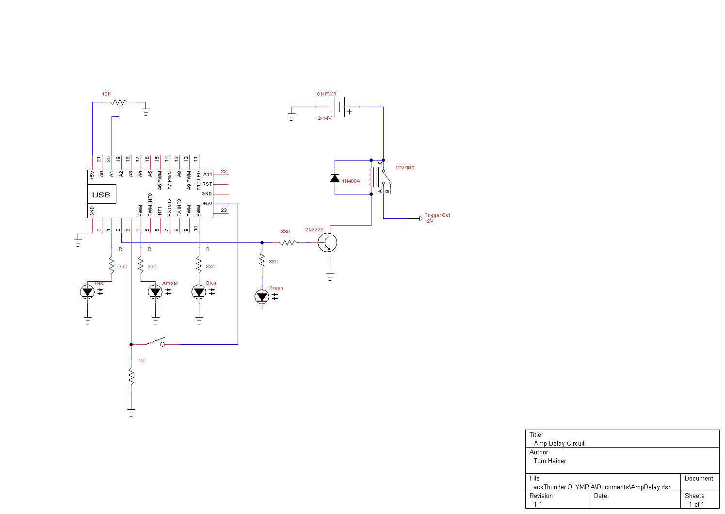
smart amp delay
This system is designed as a Windows service that detects various power events, including Suspend, Hibernate, Reboot, and Shutdown. It can send appropriate responses to a control circuit, specifically a Heartbeat or Kill signal. The trigger mechanism is also regulated...
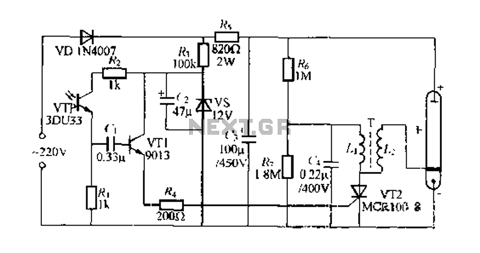
Fill light indoor photography circuit
Engaged in indoor portrait photography, practitioners often find that using a single camera can result in images lacking depth and layering. To achieve better photographic outcomes, multiple auxiliary lighting sources are typically arranged around the subject. The following describes a...
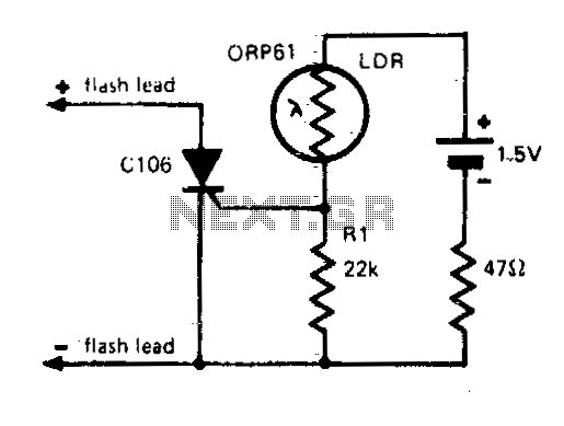
Flash slave driver
In photography, a separate flash, triggered by the light of a master flash, is often required to provide additional light and fill in shadows. The sensitivity of this circuit depends on the proximity of the master flash and the value...
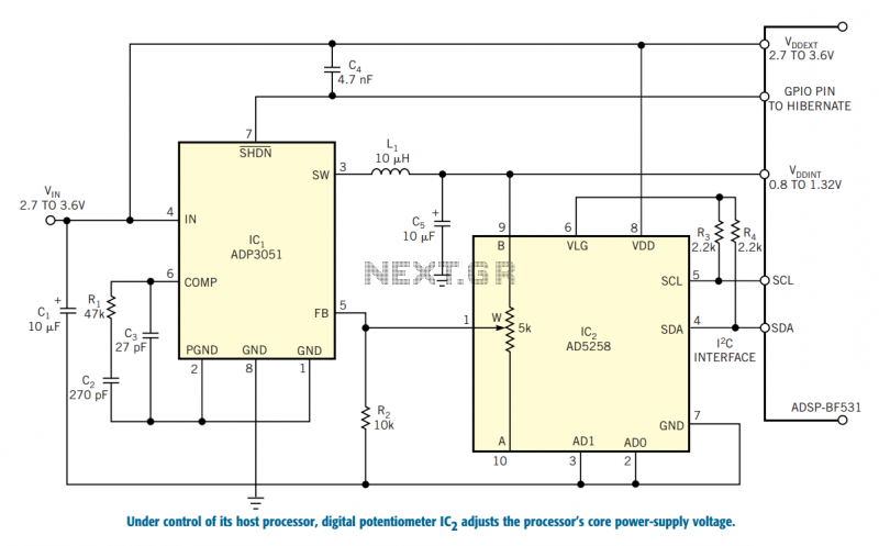
Control a processor`s power supply in real time
In battery-powered applications in which power management is key, a microprocessor may adjust its core voltage corresponding to an increase or a decrease in clock speed, allowing full processing power when necessary but not wasting excess power when idle. The...
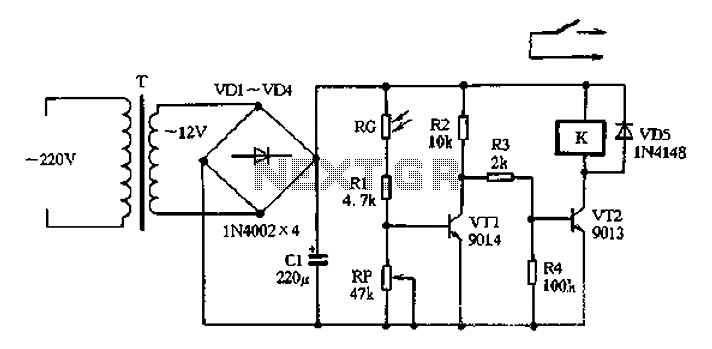
Light control relay control lamp
The circuit operates on 220V AC input, which is transformed to approximately 12V DC using a step-down transformer (T), a diode bridge rectifier (VDI-VD4), and a filter capacitor (C1). This setup is designed to power the entire circuit. The light...
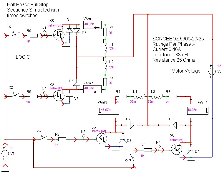
case stepper
Beige Bag Software has been offering affordable and innovative circuit design tools since 1990. B2 Spice provides schematics as well as analog, digital, and mixed-mode electronic circuit simulation. It integrates with EAGLE and CADSTAR PCB software.
B2 Spice is a powerful...
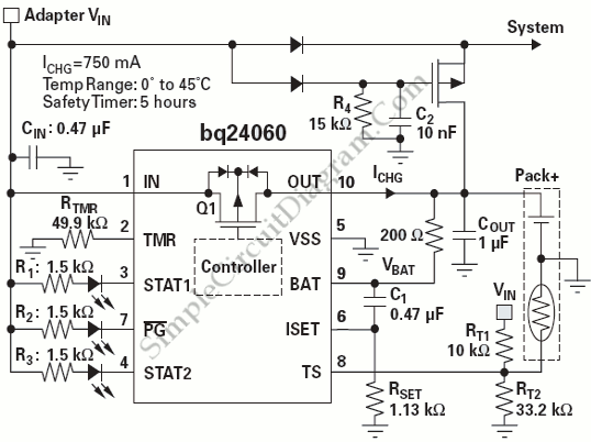
Power Path Management Battery Charger
Powering the system is required by many applications while charging the battery simultaneously. Interaction between the system and charger may result in a...
Power management in electronic systems is critical, particularly in applications that necessitate simultaneous operation and battery charging. This...
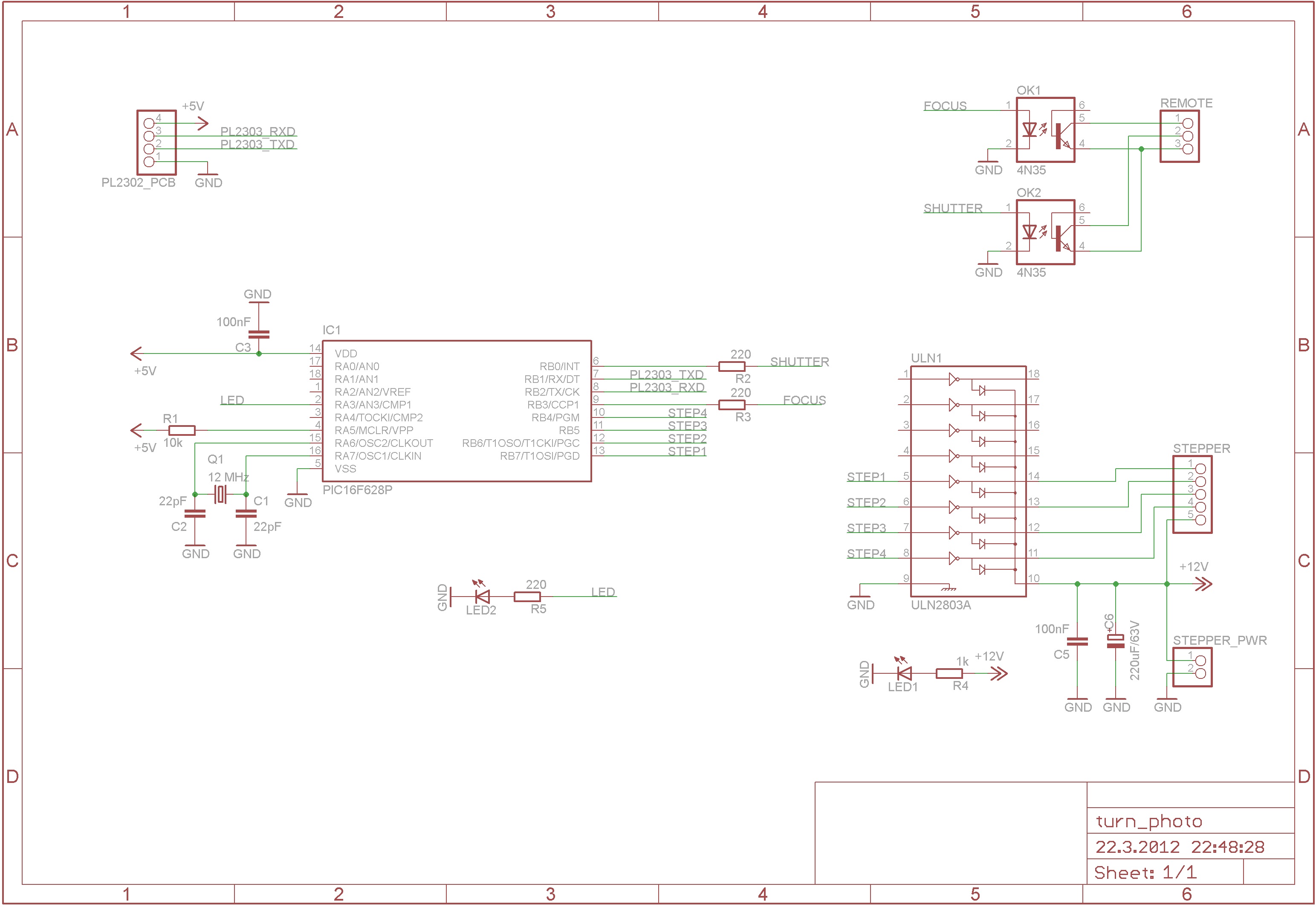
Turntable Photography Equipment
The device captures 360-degree photos, which are essentially animations made from multiple images of a product taken from different angles. It requires a controllable device that can take pictures at even intervals. As depicted in the accompanying image, a device...
Mains Manager
It is common to forget to turn off peripherals such as monitors, scanners, and printers when shutting down a PC. Typically, these devices are connected to a four-way trailing socket, which is plugged into a wall outlet. If this outlet...