


Outdoor Light Controller Circuit
#outdoor light
#neon bulb
#CdS photocell
#optocoupler
#diac/triac
#light sensor
#automated lighting
#darkness detection
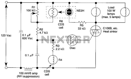
Description: A neon bulb and a CdS photocell are enclosed in a light-tight enclosure to form an optocoupler. A diac/triac combination is employed to create a snap-switch effect. A second CdS photocell serves as the primary sensor. As darkness approaches, the resistance of K4 begins to increase. Upon reaching a certain threshold level, the diac triggers the triac, causing the neon bulb to illuminate. This illumination reduces the resistance of R6, which in turn triggers the diac to activate the triac, lighting the neon bulb and supplying power to the load. As morning light increases, this process is reversed, resulting in the neon bulb turning off and the SCR shutting down.
The described circuit utilizes an optocoupler design that effectively isolates the control signal from the load while providing the necessary switching action. The neon bulb serves as an indicator and light source, while the CdS photocells function as light sensors, detecting ambient light levels. The first CdS photocell, enclosed within the light-tight enclosure, is responsible for detecting darkness and initiating the switching process.
The diac and triac configuration is crucial for achieving the snap-switch effect, where the triac remains in a conductive state until the current drops below a certain level. This allows for stable operation and prevents flickering of the neon bulb as it turns on and off. The second CdS photocell, acting as the main sensor, provides feedback to the circuit, allowing it to respond dynamically to changes in light conditions.
As ambient light decreases, the resistance of K4 rises, prompting the diac to activate the triac when the light level falls below a predetermined threshold. This triggers the neon bulb to illuminate, which consequently reduces the resistance of R6. The reduced resistance facilitates the diac's triggering of the triac, ensuring that the load receives power.
In the morning, as light levels increase, the resistance of K4 decreases, leading to the triac being turned off when the light exceeds the threshold. This results in the neon bulb extinguishing and the SCR deactivating, effectively completing the light-sensing circuit. The design is efficient for applications such as automatic lighting systems or dusk-to-dawn switches, where the circuit can control electrical loads based on ambient light conditions without manual intervention. A neon bulb and a CdS photocell enclosed in a light-tight enclosure form an optocoupler. A diac/triac combination is used to provide the snap- switch effect. A second CdS photocell acts as the main sensor. As darkness approaches, the resistance of K4 begins to increase. At a threshold level, the ciiac triggers the triac and causes the neon bulb to light. This reduces the resistance of R6, causing the diac to trigger the triac, which lights the neon bulb and provides power to the load. As morning light comes up, the process is reversed. The neon bulb goes out and the SCR turns off.
The described circuit utilizes an optocoupler design that effectively isolates the control signal from the load while providing the necessary switching action. The neon bulb serves as an indicator and light source, while the CdS photocells function as light sensors, detecting ambient light levels. The first CdS photocell, enclosed within the light-tight enclosure, is responsible for detecting darkness and initiating the switching process.
The diac and triac configuration is crucial for achieving the snap-switch effect, where the triac remains in a conductive state until the current drops below a certain level. This allows for stable operation and prevents flickering of the neon bulb as it turns on and off. The second CdS photocell, acting as the main sensor, provides feedback to the circuit, allowing it to respond dynamically to changes in light conditions.
As ambient light decreases, the resistance of K4 rises, prompting the diac to activate the triac when the light level falls below a predetermined threshold. This triggers the neon bulb to illuminate, which consequently reduces the resistance of R6. The reduced resistance facilitates the diac's triggering of the triac, ensuring that the load receives power.
In the morning, as light levels increase, the resistance of K4 decreases, leading to the triac being turned off when the light exceeds the threshold. This results in the neon bulb extinguishing and the SCR deactivating, effectively completing the light-sensing circuit. The design is efficient for applications such as automatic lighting systems or dusk-to-dawn switches, where the circuit can control electrical loads based on ambient light conditions without manual intervention. A neon bulb and a CdS photocell enclosed in a light-tight enclosure form an optocoupler. A diac/triac combination is used to provide the snap- switch effect. A second CdS photocell acts as the main sensor. As darkness approaches, the resistance of K4 begins to increase. At a threshold level, the ciiac triggers the triac and causes the neon bulb to light. This reduces the resistance of R6, causing the diac to trigger the triac, which lights the neon bulb and provides power to the load. As morning light comes up, the process is reversed. The neon bulb goes out and the SCR turns off.
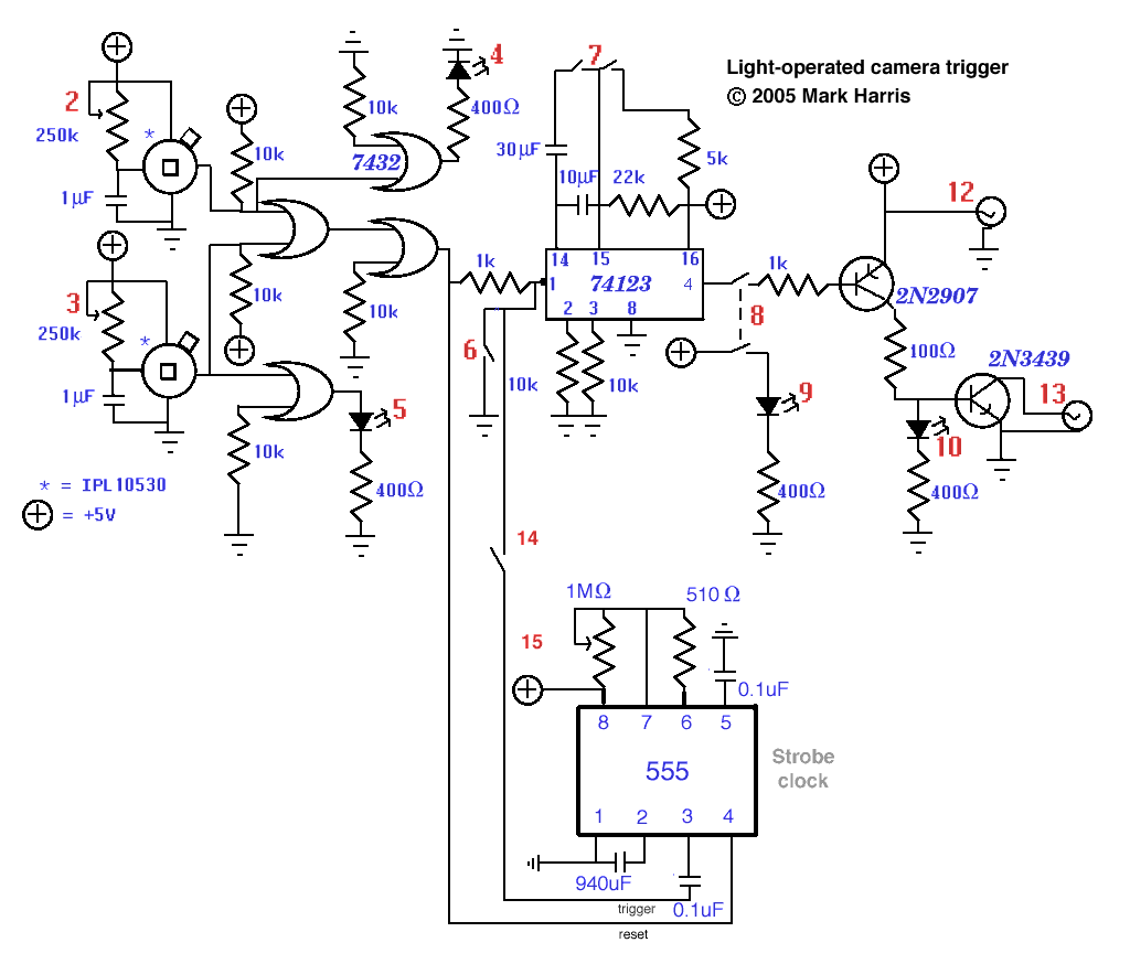
home-made light-operated camera trigger
This device is designed to capture images of moving objects by activating a camera or flashgun when one or two light beams are interrupted. Originally intended for photographing insects in flight, it can also be utilized for projectiles and other...
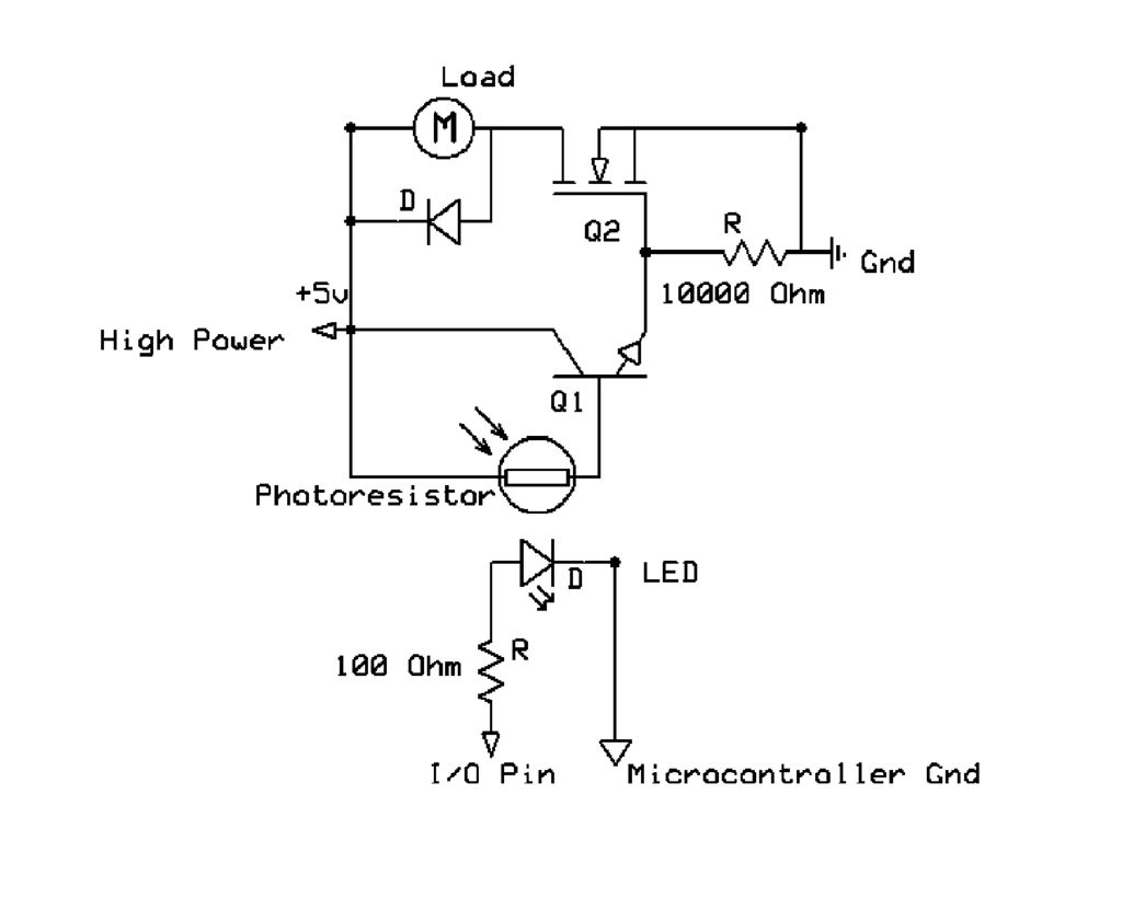
Optocoupler
This circuit utilizes a microcontroller I/O pin to control a high-power load, such as a motor, while preventing potential damage to the sensitive circuits of the microcontroller.
The described circuit employs a microcontroller to manage a high-power load, typically a motor,...
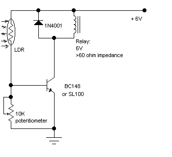
6V Light Barrier Sensor Detector
The following circuit illustrates a Light Barrier Sensor Detector Circuit Diagram. Features include a single transistor, an adjustable potentiometer, and a 6V power supply.
The Light Barrier Sensor Detector Circuit is designed to detect the presence of an object by utilizing...
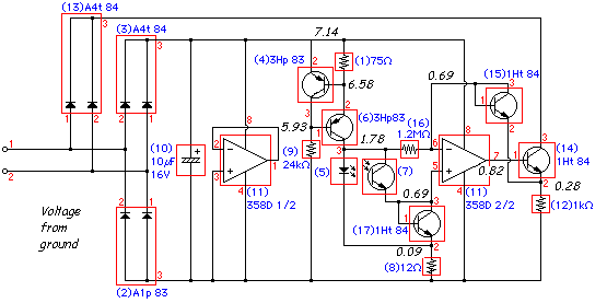
LEGO Light SensorCircuit With LM358 IC
The following circuit illustrates a LEGO Light Sensor Circuit Diagram. This circuit is based on the LM358 integrated circuit, which features a dual operational amplifier and high-speed capabilities.
The LEGO Light Sensor Circuit utilizes the LM358, a versatile dual op-amp IC,...
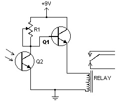
Light/Dark Detectors
This compact circuit is capable of distinguishing between light and darkness, making it highly beneficial for controlling the operation of signs, porch lights, or other devices in response to changing light conditions.
The circuit operates using a light-dependent resistor (LDR) as...
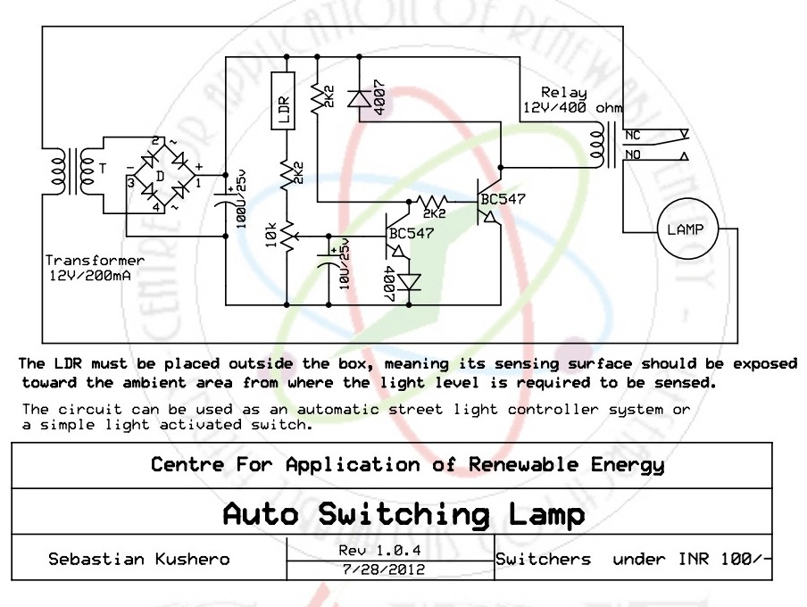
Light Activated Switch
The light-activated switch circuit can be used for switching off a particular lamp or group of lamps in response to varying ambient light levels.
The light-activated switch circuit utilizes a light-dependent resistor (LDR) as the primary sensing element to detect ambient...
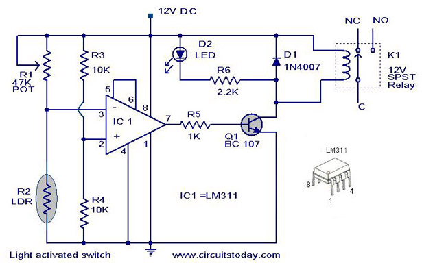
Light Activated SwitchCircuit Based On The LM311 IC
The following circuit illustrates a Light Activated Switch Circuit Diagram. This circuit is based on the LM311 integrated circuit, which functions as a voltage comparator.
The Light Activated Switch Circuit utilizes the LM311 voltage comparator to control the switching of a...
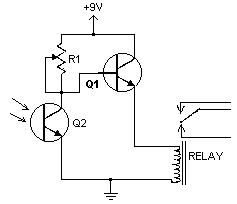
Light/Dark Detector relay
This handy little circuit can tell the difference between darkness and light, making it very useful for switching on and off signs, porch lights or other things when it gets dark or light. More: R1 Adjusts sensitivity
The circuit described is...
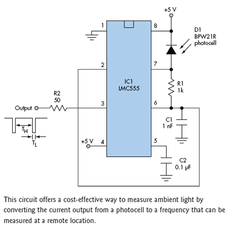
Simple Light Sensor Circuit Features High Dynamic Range
Ambient light is increasingly being utilized as an energy source. To assist designers in developing such systems, this circuit effectively measures ambient light intensity across four decades of measurement. The design is cost-effective, and with the sensor housed in a...