


Photosensitive resistor circuit diagram of an automatic lighting
#photosensitive resistor
#automatic lighting
#light sensor
#energy saving
#public places
#dormitories
#hospitals
#circuit diagram
#light control
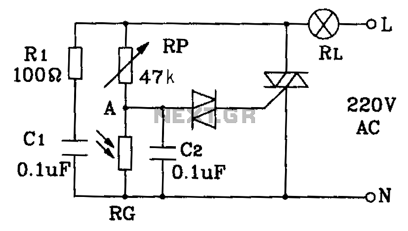
Description: This circuit diagram illustrates an automatic lighting system designed for use in hospitals, dormitories, corridors, and public spaces. The system utilizes a photosensitive resistor to control the lighting, ensuring that lights are automatically turned off during the day and activated at night.
The automatic lighting circuit employs a photosensitive resistor (LDR) as the primary sensor, which detects ambient light levels. When the light intensity falls below a predetermined threshold, typically at dusk, the LDR's resistance increases, triggering the circuit to activate the lighting system. Conversely, during daylight hours, the increased light intensity causes the LDR's resistance to decrease, which in turn deactivates the lights.
The circuit can be designed using a simple transistor switch or a relay, depending on the required load capacity. For smaller loads, a transistor such as a NPN type can be used, where the LDR is connected in a voltage divider configuration with a fixed resistor. The output from the divider is fed into the base of the transistor. When the resistance of the LDR increases at low light levels, sufficient base current flows, allowing the transistor to conduct and turn on the connected load, such as LED lights or fluorescent lamps.
For larger loads, a relay can be employed. The LDR and fixed resistor create a similar voltage divider, which activates a relay coil when the ambient light is low. The relay then closes its contacts, allowing mains power to flow to the lighting fixtures. This configuration provides isolation from high voltage and can handle larger currents safely.
To enhance functionality, additional components such as a timer or a microcontroller can be integrated into the circuit. This allows for more complex behaviors, such as dimming the lights or setting specific on/off schedules based on time rather than just light levels.
Overall, this automatic lighting system is efficient and practical for environments requiring reliable illumination during nighttime or low-light conditions, contributing to safety and convenience in various public and private settings. By the photosensitive resistor of this circuit is a circuit diagram of the automatic lighting for hospitals, dormitories corridor and public places. It automatically lights off during the day and at night.
The automatic lighting circuit employs a photosensitive resistor (LDR) as the primary sensor, which detects ambient light levels. When the light intensity falls below a predetermined threshold, typically at dusk, the LDR's resistance increases, triggering the circuit to activate the lighting system. Conversely, during daylight hours, the increased light intensity causes the LDR's resistance to decrease, which in turn deactivates the lights.
The circuit can be designed using a simple transistor switch or a relay, depending on the required load capacity. For smaller loads, a transistor such as a NPN type can be used, where the LDR is connected in a voltage divider configuration with a fixed resistor. The output from the divider is fed into the base of the transistor. When the resistance of the LDR increases at low light levels, sufficient base current flows, allowing the transistor to conduct and turn on the connected load, such as LED lights or fluorescent lamps.
For larger loads, a relay can be employed. The LDR and fixed resistor create a similar voltage divider, which activates a relay coil when the ambient light is low. The relay then closes its contacts, allowing mains power to flow to the lighting fixtures. This configuration provides isolation from high voltage and can handle larger currents safely.
To enhance functionality, additional components such as a timer or a microcontroller can be integrated into the circuit. This allows for more complex behaviors, such as dimming the lights or setting specific on/off schedules based on time rather than just light levels.
Overall, this automatic lighting system is efficient and practical for environments requiring reliable illumination during nighttime or low-light conditions, contributing to safety and convenience in various public and private settings. By the photosensitive resistor of this circuit is a circuit diagram of the automatic lighting for hospitals, dormitories corridor and public places. It automatically lights off during the day and at night.
Light Sensor
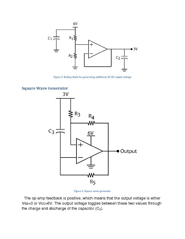
The report provides information related to light sensors, photoresistors, comparators, and associated circuits. It contains extensive details regarding detection.
Light sensors are devices that detect and respond to light levels in the environment. A common type of light sensor is the...
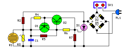
Dark Activated Terrace Lamp
This is a compact circuit that can be wired in parallel with existing switches. The device enables one or more lamps to illuminate at sunset and turn off at dawn. It incorporates components Q1 and Q2.
The circuit is designed to...
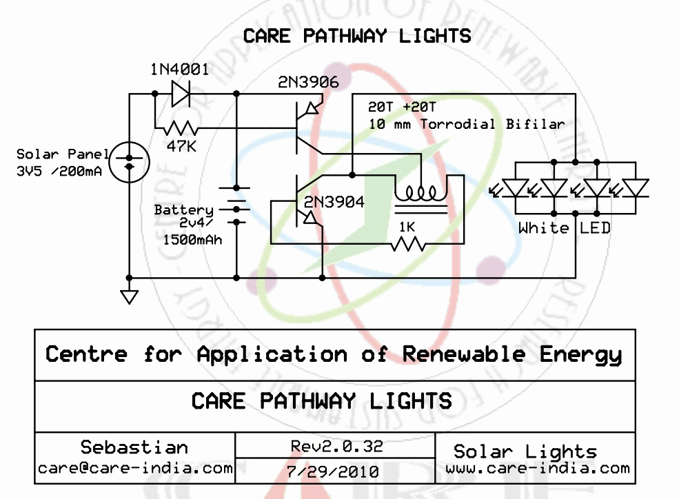
Energy Saving Lighting with One-Shot Timer Circuit
Engineer Radu Preda from Romania has developed two energy-saving lighting circuits designed to control the duration that lights are activated, ultimately aiming to reduce electricity expenses. The first circuit utilizes a relay, while the second employs an optoisolator triac (MOC3041)...
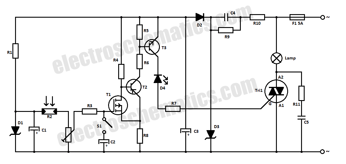
Automatic Light Switch Circuit
This light-sensitive automatic light switch circuit is designed to be connected to the main 220V supply. The circuit will activate a 220V lamp during nighttime.
The light-sensitive automatic light switch circuit operates by utilizing a light-dependent resistor (LDR) to detect ambient...
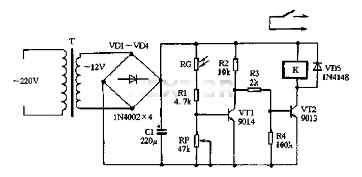
Light control relay control lamp
The circuit operates on 220V AC input, which is transformed to approximately 12V DC using a step-down transformer (T), a diode bridge rectifier (VDI-VD4), and a filter capacitor (C1). This setup is designed to power the entire circuit. The light...
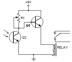
Light/Dark Detector relay
This handy little circuit can tell the difference between darkness and light, making it very useful for switching on and off signs, porch lights or other things when it gets dark or light. More: R1 Adjusts sensitivity
The circuit described is...
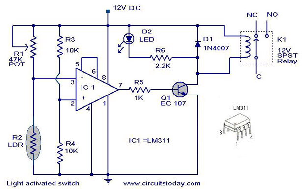
Light Activated SwitchCircuit Based On The LM311 IC
The following circuit illustrates a Light Activated Switch Circuit Diagram. This circuit is based on the LM311 integrated circuit, which functions as a voltage comparator.
The Light Activated Switch Circuit utilizes the LM311 voltage comparator to control the switching of a...
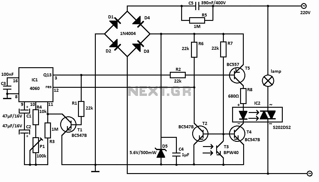
Light sensor switch circuit
This light sensor switch circuit enables the automatic activation of a lamp when ambient light levels decrease, such as during nightfall. The duration for which the lamp remains on can be adjusted using potentiometer P1, with a range of 1...
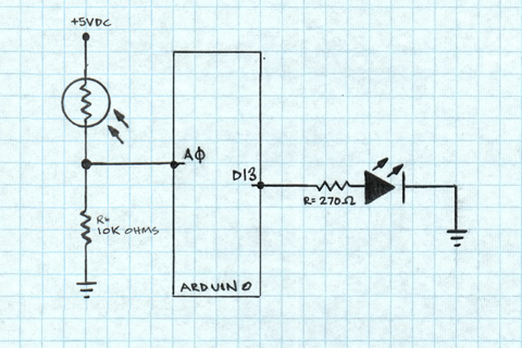
Arduino Light Sensors
A project is underway to determine the number of sun hours available at a specific location and to track this data over time as part of solar power installation design. The concept involves utilizing a light detector exposed to sunlight...