


SH-123 ASIC holiday lights
#holiday lights
#220V AC
#bridge rectifier
#filter capacitor
#resistor
#LED
#lighting
#power supply
#holiday decoration
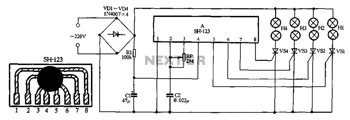
Description: A 220V AC input is processed by a bridge rectifier consisting of diodes VD1 to VD4, which supplies electricity to four lights labeled H1 to H4. The circuit includes a limiting resistor R1 and a filter capacitor C1 to stabilize the output voltage. The circuit is designed to provide four controllable outputs, LI to L4, which can be sequentially turned on and off to create an effect of movement among the lights H1 to H4, simulating a racing scenario. A potentiometer RP is included to adjust the flow rate of the lights H1 to H4.
The circuit begins with the 220V AC input, which is directed to a bridge rectifier formed by diodes VD1 through VD4. This configuration converts the alternating current (AC) into direct current (DC), ensuring a consistent voltage supply for the subsequent components. The output from the rectifier is then smoothed by filter capacitor C1, which reduces voltage ripple and provides a more stable DC voltage.
Resistor R1 serves as a current limiting component, ensuring that the current flowing to the lights H1 to H4 does not exceed safe operating levels, thereby protecting the LEDs or bulbs from potential damage. The four outputs, LI to L4, are designed to control the operation of the lights in a sequential manner. This can be achieved using a microcontroller or a simple relay-based control circuit, allowing for the lights to be turned on and off in a programmed sequence.
The use of potentiometer RP allows for user adjustment of the flow rate, which in turn affects the timing of the lights' operation. By varying the resistance of RP, the duration for which each light remains on or off can be modified, creating different visual effects that simulate the excitement of a horse racing event. This feature adds an element of interactivity to the circuit, as users can customize the speed and behavior of the light sequence according to their preferences.
Overall, this circuit design provides an effective means of creating dynamic lighting effects suitable for entertainment applications, combining basic electronic components to achieve a visually appealing output.220V AC by VD1-VD4 bridge rectifier, all the way to supply four lights Hl - H4 electricity, another pass resistance Rl buck limit, filter capacitor C1 supply manifold A electri city. Manifold 4 outputs LI-L4 direct drive controllable VSl ~ VS4 sequentially turned on and off so that the lights were lit H1 ~ H4 light, forming a sense of movement in Happy Valley. Adjust potentiometer R P resistance can change four lights H1 ~ H4 flow rate of horse racing.
The circuit begins with the 220V AC input, which is directed to a bridge rectifier formed by diodes VD1 through VD4. This configuration converts the alternating current (AC) into direct current (DC), ensuring a consistent voltage supply for the subsequent components. The output from the rectifier is then smoothed by filter capacitor C1, which reduces voltage ripple and provides a more stable DC voltage.
Resistor R1 serves as a current limiting component, ensuring that the current flowing to the lights H1 to H4 does not exceed safe operating levels, thereby protecting the LEDs or bulbs from potential damage. The four outputs, LI to L4, are designed to control the operation of the lights in a sequential manner. This can be achieved using a microcontroller or a simple relay-based control circuit, allowing for the lights to be turned on and off in a programmed sequence.
The use of potentiometer RP allows for user adjustment of the flow rate, which in turn affects the timing of the lights' operation. By varying the resistance of RP, the duration for which each light remains on or off can be modified, creating different visual effects that simulate the excitement of a horse racing event. This feature adds an element of interactivity to the circuit, as users can customize the speed and behavior of the light sequence according to their preferences.
Overall, this circuit design provides an effective means of creating dynamic lighting effects suitable for entertainment applications, combining basic electronic components to achieve a visually appealing output.220V AC by VD1-VD4 bridge rectifier, all the way to supply four lights Hl - H4 electricity, another pass resistance Rl buck limit, filter capacitor C1 supply manifold A electri city. Manifold 4 outputs LI-L4 direct drive controllable VSl ~ VS4 sequentially turned on and off so that the lights were lit H1 ~ H4 light, forming a sense of movement in Happy Valley. Adjust potentiometer R P resistance can change four lights H1 ~ H4 flow rate of horse racing.
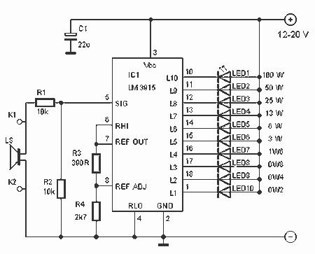
10 LED Audio Amplifier Power-meter
This indicator lets you see how much power an amplifier produces. The circuit uses an LM 3915, the logarithmic variation of the known IC LED VU Meter LM 3914. The circuit is connected directly to the speaker output of amplifier...
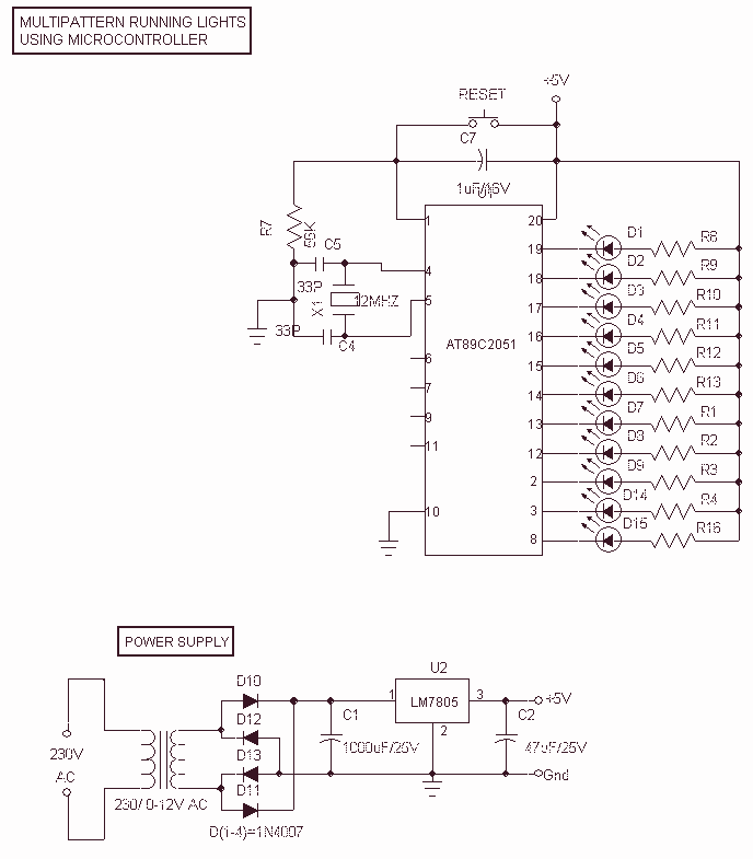
Multipattern Running LEDs
This Project Multi-Pattern Running light is used to generate several designs of Running Lights. We use ten LEDs for display. The designs can be selected by using two switches UP and DOWN. The 8 bit Microcontroller is used to control...
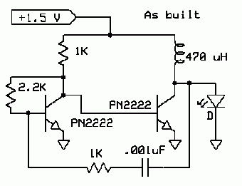
LED Boost Circuit
The completed board may be driven by voltages between 0.8 and 3 Volts. While the basic design goal was candle-like light from a single cell, the values used were chosen to allow safe operation from 3 Volts so you can,...
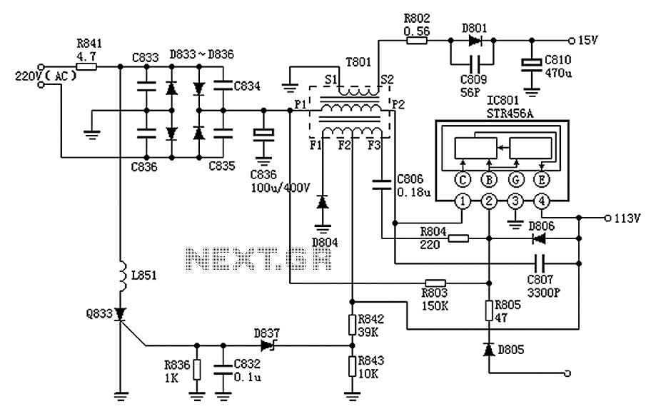
Panasonic M12H switching power supply circuit diagram
The Panasonic M12H switching power supply circuit is utilized in Panasonic models such as TC-230H, TC-2030DHN, TC-830D, and TC-840D. The circuit operates with an oscillation frequency that generates approximately 300V DC voltage at C836. The T801 transformer is involved in...
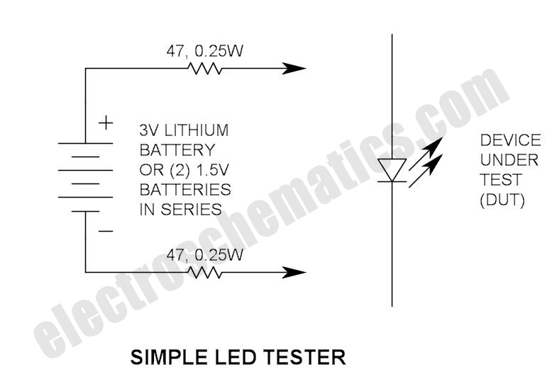
Simple LED Tester
Do not let its extreme simplicity deceive you — this device is useful! Many have been made over the years, and some have even been given away as gifts. Yes, multimeter...
A multimeter is an essential instrument in electronics, used for...
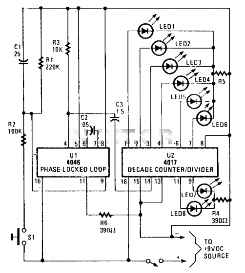
LED Electronic roulette
The circuit utilizes a 4046 Phase-Locked Loop (PLL) that incorporates a voltage-controlled oscillator (VCO), two phase comparators, a source follower, and a Zener diode to generate a low-frequency pulsed output of approximately 40 Hz. The frequency range of the VCO...
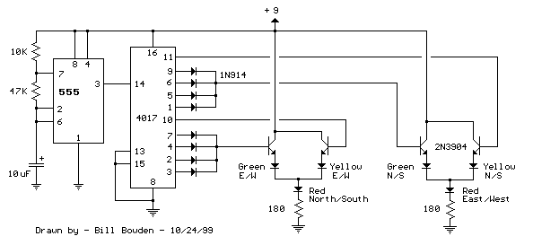
LED Traffic Lights for Games with 555
The LED traffic Light circuit controls 6 LEDs (red, yellow and green) for both north/south directions and east/west directions. The timing sequence is generated using a CMOS 4017 decade counter and a 555 timer. Counter outputs 1 through 4 are...
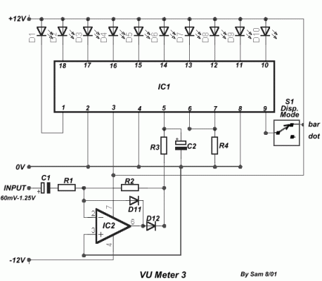
VU Meter 3
A very simple circuit for indicating levels, utilizing 10 LEDs. The circuit employs a precision half-wave rectification around the IC2, with a gain of one. The switch S1 allows for the selection of which LED to indicate. The input level...
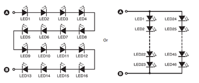
16 led46 led circuit combination
A series combination of 16 LEDs provides a luminance (lux) equivalent to a 12W bulb. However, if two series combinations of 23 LEDs are connected in parallel (totaling 46 LEDs), the output is equivalent to a 35W light bulb. Diode...