


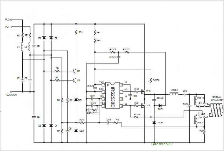
Simplified Three Level Dimming Cfl Fluorescent Ballast Using The Irs2530d
#fluorescent ballast
#sine wave
#oscillator
#IRS2530D
#dimming
#CFL
#circuit design
#audio testing
#calibration equipment
#transducer
Description: Generating and manipulating sine wave functions is a common challenge faced by circuit designers. Sine wave circuits present significant design difficulties because they function as continuously controlled linear oscillators. Such circuitry is essential in various fields, including audio testing, calibration equipment, transducer drives, power conditioning, and automatic test equipment (ATE). Often, control over frequency, amplitude, or distortion level is required, and in many applications, all three parameters must be managed simultaneously. A range of techniques employing both analog and digital methods are available for different applications. Each circuit approach possesses distinct strengths and weaknesses that must be aligned with the specific requirements of the application.
Generating and manipulating sine wave functions is critical in various electronic applications, necessitating a comprehensive understanding of circuit design principles. Sine wave circuits, functioning as linear oscillators, are essential in ensuring the stability and reliability of signal generation across multiple domains. The challenge lies in designing circuits that can accurately produce sine waves while allowing for precise control over key parameters such as frequency, amplitude, and distortion.
In audio testing, for instance, sine wave generators must produce clean signals with minimal distortion to ensure accurate testing of audio equipment. Similarly, in calibration equipment, sine waves are used to verify the performance of various devices, requiring high precision and fidelity. Transducer drives often utilize sine wave outputs to ensure smooth operation and efficiency, while power conditioning applications necessitate sine wave generation to maintain the quality of power supply.
To achieve the desired sine wave characteristics, designers can employ a variety of techniques. Analog methods may include the use of operational amplifiers, phase-locked loops, and Wien bridge oscillators, each offering unique advantages in terms of simplicity, cost, and performance. Digital approaches, on the other hand, often leverage microcontrollers or digital signal processors (DSPs) to generate sine waves with high precision and flexibility, allowing for easy adjustments to frequency and amplitude.
When selecting a specific circuit design, it is crucial to consider the inherent strengths and weaknesses of each approach. For example, while analog circuits may provide lower noise levels and simpler designs, they might lack the versatility and programmability offered by digital solutions. Conversely, digital circuits can introduce quantization noise and require more complex components. Ultimately, the choice of circuit design must align with the specific requirements of the application, ensuring optimal performance and reliability in sine wave generation and manipulation.Producing and manipulating the sine wave function is a com- mon problem encountered by circuit designers. Sine wave circuits pose a significant design challenge because they rep- resent a constantly controlled linear Oscillator Sine wave circuitry is required in a number of diverse areas, including Audio testing, calibration equipment, transducer
drives, power conditioning and Automatic test equipment (ATE). Control of frequency, amplitude or distortion level is often required and all three parameters must be simultaneously controlled in many applications. A number of techniques utilizing both Analog and digital ap- proaches are available for a variety of applications.
Each individual circuit approach has inherent strengths and weak- nesses which must be matched against any given application (see table).
Generating and manipulating sine wave functions is critical in various electronic applications, necessitating a comprehensive understanding of circuit design principles. Sine wave circuits, functioning as linear oscillators, are essential in ensuring the stability and reliability of signal generation across multiple domains. The challenge lies in designing circuits that can accurately produce sine waves while allowing for precise control over key parameters such as frequency, amplitude, and distortion.
In audio testing, for instance, sine wave generators must produce clean signals with minimal distortion to ensure accurate testing of audio equipment. Similarly, in calibration equipment, sine waves are used to verify the performance of various devices, requiring high precision and fidelity. Transducer drives often utilize sine wave outputs to ensure smooth operation and efficiency, while power conditioning applications necessitate sine wave generation to maintain the quality of power supply.
To achieve the desired sine wave characteristics, designers can employ a variety of techniques. Analog methods may include the use of operational amplifiers, phase-locked loops, and Wien bridge oscillators, each offering unique advantages in terms of simplicity, cost, and performance. Digital approaches, on the other hand, often leverage microcontrollers or digital signal processors (DSPs) to generate sine waves with high precision and flexibility, allowing for easy adjustments to frequency and amplitude.
When selecting a specific circuit design, it is crucial to consider the inherent strengths and weaknesses of each approach. For example, while analog circuits may provide lower noise levels and simpler designs, they might lack the versatility and programmability offered by digital solutions. Conversely, digital circuits can introduce quantization noise and require more complex components. Ultimately, the choice of circuit design must align with the specific requirements of the application, ensuring optimal performance and reliability in sine wave generation and manipulation.Producing and manipulating the sine wave function is a com- mon problem encountered by circuit designers. Sine wave circuits pose a significant design challenge because they rep- resent a constantly controlled linear Oscillator Sine wave circuitry is required in a number of diverse areas, including Audio testing, calibration equipment, transducer
drives, power conditioning and Automatic test equipment (ATE). Control of frequency, amplitude or distortion level is often required and all three parameters must be simultaneously controlled in many applications. A number of techniques utilizing both Analog and digital ap- proaches are available for a variety of applications.
Each individual circuit approach has inherent strengths and weak- nesses which must be matched against any given application (see table).
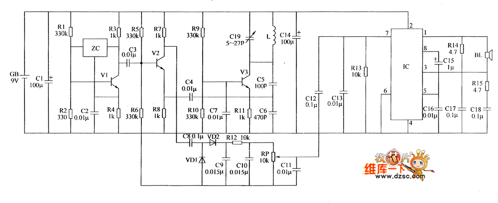
Metal detector circuit diagram 1
The metal detector circuit includes a fixed frequency oscillator, mixer, detector, detection oscillator, and power amplifier circuit. The fixed frequency oscillator circuit is composed of a ceramic filter (ZC), transistor (V1), resistors (R1 to R4), capacitor (C2), and other components....
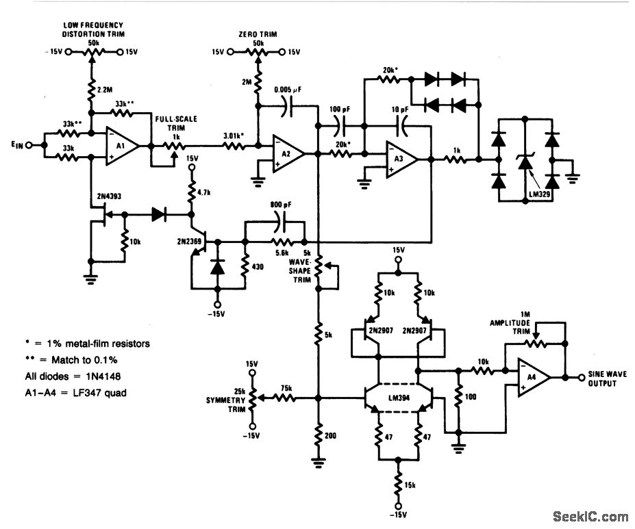
Voltage controlled sine wave oscillator
For a 0- to 10-V input, this circuit generates sine-wave outputs ranging from 1 Hz to 20 kHz, achieving linearity better than 0.2%. The distortion level is approximately 0.4%, and both the frequency and amplitude of the sine-wave output respond...
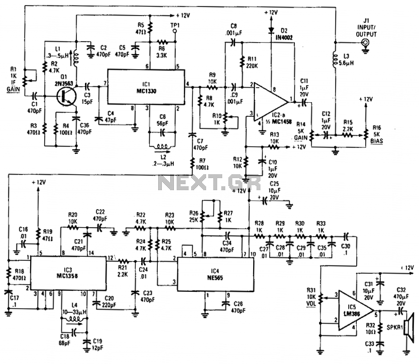
Sine wave descrambler
This decoder incorporates a sine wave recovery channel and utilizes a PIN diode attenuator driven by the sine wave recovery system to eliminate the sine wave sync suppression signal. Additionally, it functions as a sine wave descrambler.
The decoder's sine wave...
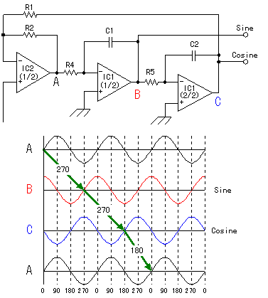
sine/cosine wave oscillator
When an alternating current signal is applied to a capacitor, the phase of the charging current and the voltage across the capacitor shifts by 90 degrees. Conversely, when an alternating current signal is applied to an inductor, the voltage change...
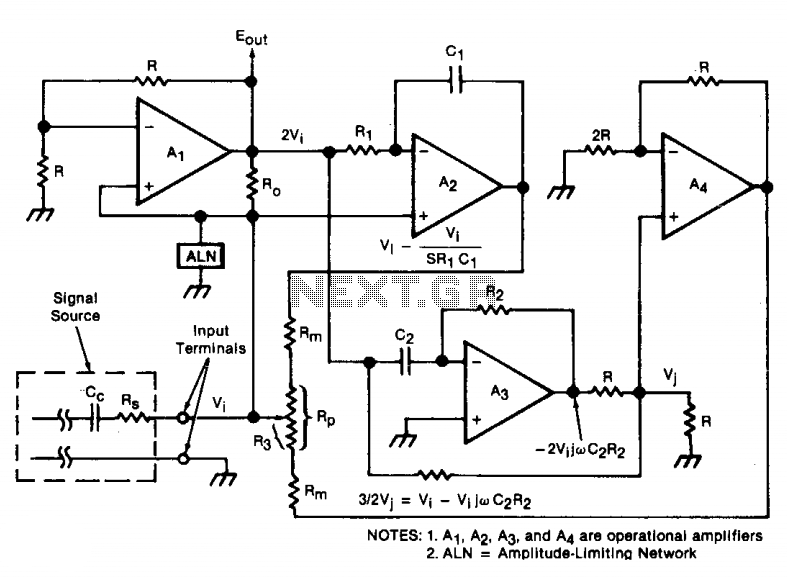
Wide frequency oscillator
An oscillator/amplifier is resistively tunable over a wide frequency range. Feedback circuits containing operational amplifiers, resistors, and capacitors synthesize the electrical effects of inductance and capacitance in parallel between the input terminals. The synthetic inductance and capacitance, and therefore the...
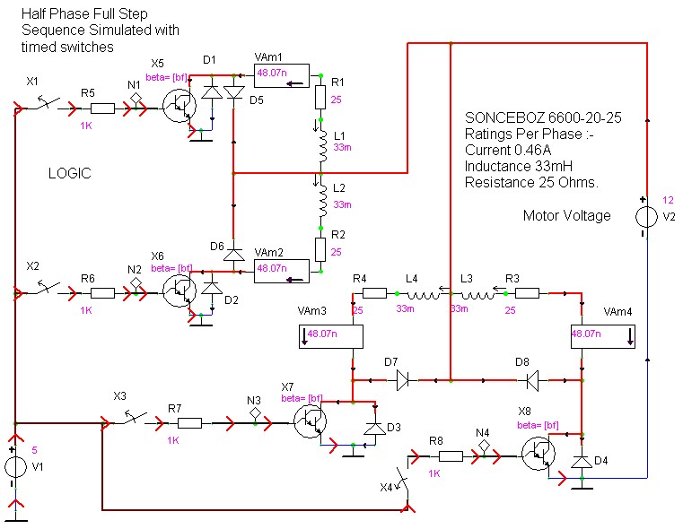
case stepper
Beige Bag Software has been offering affordable and innovative circuit design tools since 1990. B2 Spice provides schematics as well as analog, digital, and mixed-mode electronic circuit simulation. It integrates with EAGLE and CADSTAR PCB software.
B2 Spice is a powerful...
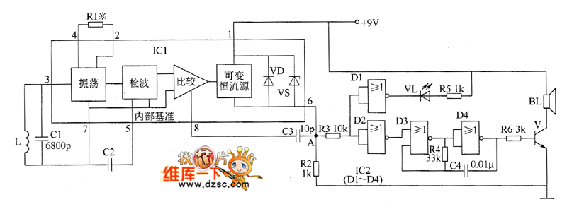
Metal detector circuit diagram 5
The metal detector circuit comprises an oscillator and a sound-light alarm circuit. The oscillator circuit includes an inductor (L), a capacitor (C1), a sensor switch integrated circuit (IC1) that integrates the oscillator, detector, comparator circuit, and peripheral components. The sound-light...
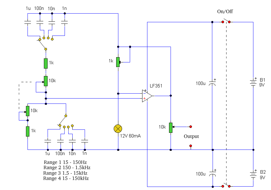
Wien oscillator
Construct a sine wave generator using the TL082 operational amplifier and a 9V power supply. However, the output is producing a distorted waveform rather than a clean sine wave. There is a need for a list of components suitable for...
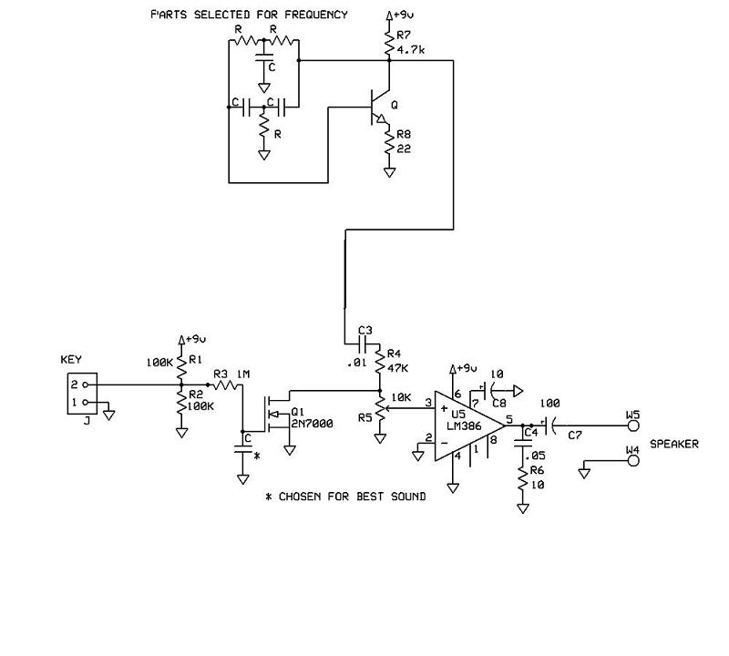
Sine wave code practice oscillator
A schematic for a code practice oscillator is needed, which can be connected to a keyer. The desired setup involves using a Picokeyer, allowing the oscillator to be plugged into the key jack of the Picokeyer. The output should drive...