


Sound-Activated Lamp (Relay/Switch)
#sound-activated
#relay
#switch
#audio amplifier
#microphone
#LED
#disco light
#sensitivity adjustment
#automotive lighting
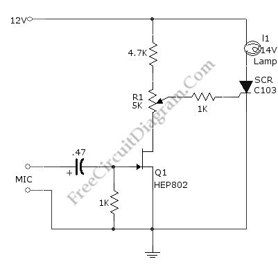
Description: This simple circuit, as shown in the schematic diagram, activates a switch using sound. It can be utilized for various applications, such as automatic sound-controlled disco lights or a car's LED light show. The transistor Q1 amplifies the audio signal from the microphone. The resistor R1 is used to adjust the peak signal to greater than approximately 0.7 volts, functioning as a sensitivity adjuster. At a certain level, the signal from the microphone, after amplification by Q1, will trigger the SCR and illuminate lamp I1. If the lamp is replaced with a relay, a sound-activated relay/switch can be obtained, which can control more powerful or high-wattage, high-voltage lamps. When using a relay, it is advisable to place a 1N4007 diode in parallel with the relay coil to prevent back EMF from damaging the SCR.
This circuit operates on the principle of sound detection and signal amplification. The microphone picks up ambient sound, converting it into an electrical signal. The transistor Q1, typically configured as a common-emitter amplifier, boosts this signal to a sufficient level. The resistor R1 plays a crucial role in setting the sensitivity of the circuit; by adjusting its value, the threshold at which the circuit responds to sound can be fine-tuned.
Once the amplified signal exceeds the predetermined threshold, it activates the silicon-controlled rectifier (SCR), which acts as a switch. The SCR allows current to flow through the load, in this case, lamp I1, effectively turning it on. This configuration is particularly useful in applications where visual indicators are needed in response to sound, such as in entertainment or decorative lighting systems.
For applications requiring control of higher power devices, substituting lamp I1 with a relay is recommended. The relay can handle larger currents and voltages, making it suitable for controlling high-wattage lamps or other electrical devices. The inclusion of a 1N4007 diode across the relay coil is essential to protect the SCR from voltage spikes generated when the relay coil is de-energized. This diode provides a path for the back EMF, ensuring reliable operation and longevity of the SCR within the circuit.
In summary, this sound-activated switch circuit is versatile and can be adapted for various applications, from simple lighting control to more complex automation systems, emphasizing the importance of component selection and configuration in achieving desired performance outcomes.This simple circuit shown int the schematic diagram actives the switch using sound. We can use this circuit for various applications, such as automatic (sound-controlled) disco light or car`s LED light show. The Q1 amplify the audio from mic. The R1 is used to adjust the peak of signal to greater than about 0. 7 volts, act as sensitivity adjuster. A certain level, the signal coming from microphone, after amplification by Q1, will trigger the SCR and light lamp I1. If we change the lamp with a relay, then we can get a sound-activated relay/switch, which can be used to control more powerful / high wattage high voltage lamps.
If we use a relay, place a 1N4007 diode in parallel with the relay coil to prevent the back-emf from relay coil destroying the SCR. Here is the schematic diagram of the circuit:
This circuit operates on the principle of sound detection and signal amplification. The microphone picks up ambient sound, converting it into an electrical signal. The transistor Q1, typically configured as a common-emitter amplifier, boosts this signal to a sufficient level. The resistor R1 plays a crucial role in setting the sensitivity of the circuit; by adjusting its value, the threshold at which the circuit responds to sound can be fine-tuned.
Once the amplified signal exceeds the predetermined threshold, it activates the silicon-controlled rectifier (SCR), which acts as a switch. The SCR allows current to flow through the load, in this case, lamp I1, effectively turning it on. This configuration is particularly useful in applications where visual indicators are needed in response to sound, such as in entertainment or decorative lighting systems.
For applications requiring control of higher power devices, substituting lamp I1 with a relay is recommended. The relay can handle larger currents and voltages, making it suitable for controlling high-wattage lamps or other electrical devices. The inclusion of a 1N4007 diode across the relay coil is essential to protect the SCR from voltage spikes generated when the relay coil is de-energized. This diode provides a path for the back EMF, ensuring reliable operation and longevity of the SCR within the circuit.
In summary, this sound-activated switch circuit is versatile and can be adapted for various applications, from simple lighting control to more complex automation systems, emphasizing the importance of component selection and configuration in achieving desired performance outcomes.This simple circuit shown int the schematic diagram actives the switch using sound. We can use this circuit for various applications, such as automatic (sound-controlled) disco light or car`s LED light show. The Q1 amplify the audio from mic. The R1 is used to adjust the peak of signal to greater than about 0. 7 volts, act as sensitivity adjuster. A certain level, the signal coming from microphone, after amplification by Q1, will trigger the SCR and light lamp I1. If we change the lamp with a relay, then we can get a sound-activated relay/switch, which can be used to control more powerful / high wattage high voltage lamps.
If we use a relay, place a 1N4007 diode in parallel with the relay coil to prevent the back-emf from relay coil destroying the SCR. Here is the schematic diagram of the circuit:
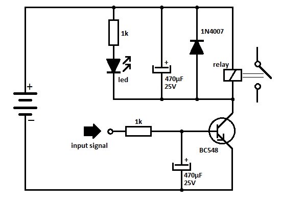
Transistor Relay Driver Circuit
One of the serious problems in relay-operated circuits is the relay clicking or chattering during the on/off operation of the relay driver transistor. This issue can lead to unreliable circuit performance and may cause premature wear of the relay contacts.
In...
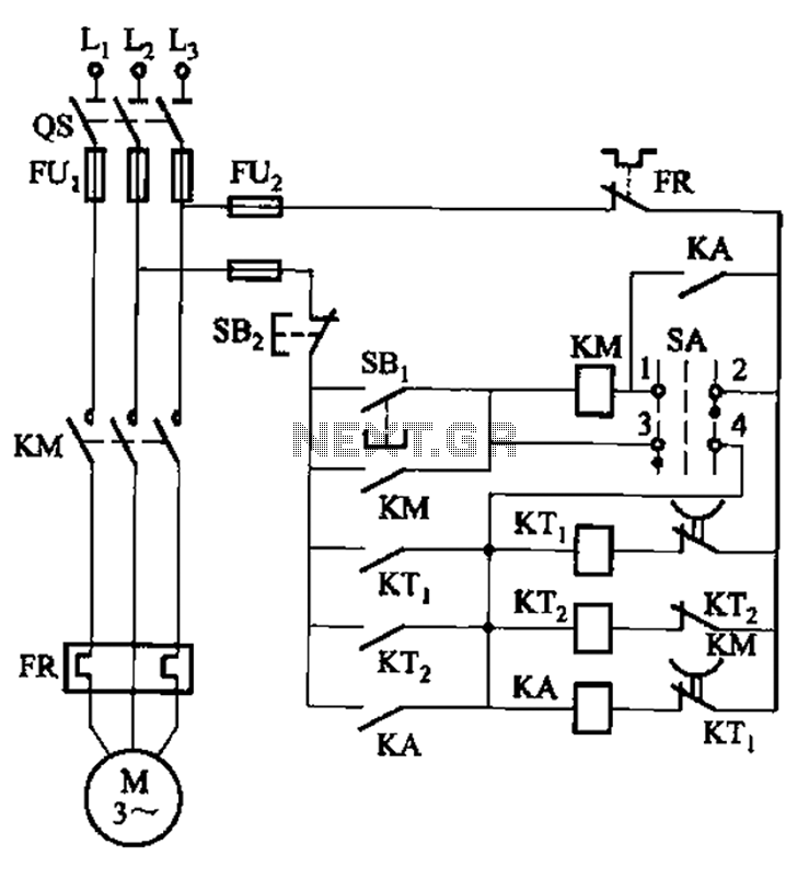
Third batch start and stop cycle control circuits
The circuit illustrated in Figure 3-78 utilizes two relays for automatic control, featuring a more complex line structure. This configuration allows for intermittent motor operation. Additionally, it can operate continuously when switch SA is positioned to the right.
The circuit employs...
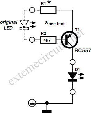
Case Modding
The aesthetics of case modding, which involves modifying a PC's enclosure, provide ample opportunities for discussion and original circuit designs. Low current LED indicators are typically installed in PC enclosures. While this approach conserves energy, the LEDs do not emit...
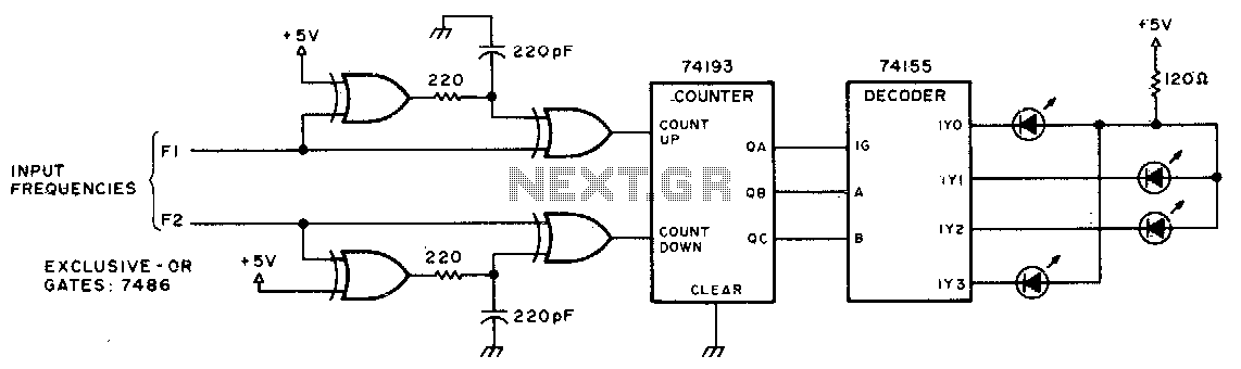
Beat frequency indicator
This circuit utilizes LEDs to visualize the beat frequency generated by two-tone oscillators. At any given moment, only one LED is illuminated, and the perceived rotation of the light dot accurately reflects the beat frequency. When f1 is greater than...
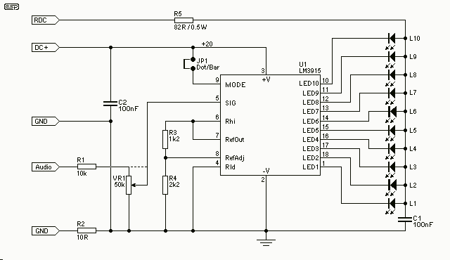
LED Audio VU Meter
This project is also an essential part of the expandable analyser to be published soon or perhaps eventually, and one meter circuit is used for each frequency band. There are many other uses for a simple LED VU meter. They...
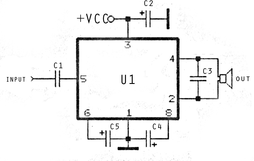
mini and simple power amplifier
The image above depicts a miniature audio amplifier that is quite simple in design. A schematic for this audio amplifier is provided, which requires only a few components, as detailed in the accompanying diagram. This amplifier is inexpensive to construct...
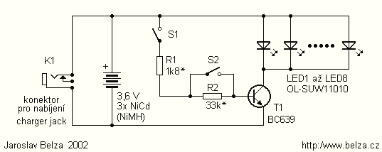
Powerful LED Flashlight circuit
Presented circuit is very simple. With more sampling, I refrained from using the converter and lamp designed for powering three NiCd or NiMH batteries. Because the voltage difference between the battery and the LED is very small, this arrangement is...
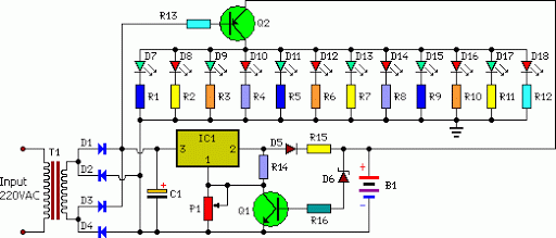
automatic low power emergancy light
An emergency light system utilizing white LEDs, which provides several advantages: 1. It is highly bright due to the use of white LEDs. 2. The light activates automatically during a mains power failure and deactivates when mains power is restored....
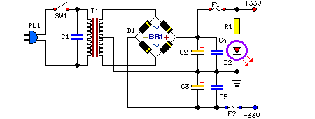
25 Watt Audio Amplifier
This is a 25 Watt basic power amplifier designed to be relatively easy to build at a reasonable cost. It offers better performance than standard STK module amplifiers commonly found in mass-market stereo receivers. The original design was created to...