


SR63 holiday lights ASIC
#holiday lights
#ASIC
#220V AC
#bridge rectifier
#voltage regulator
#LED
#lighting
#power supply
#DIY
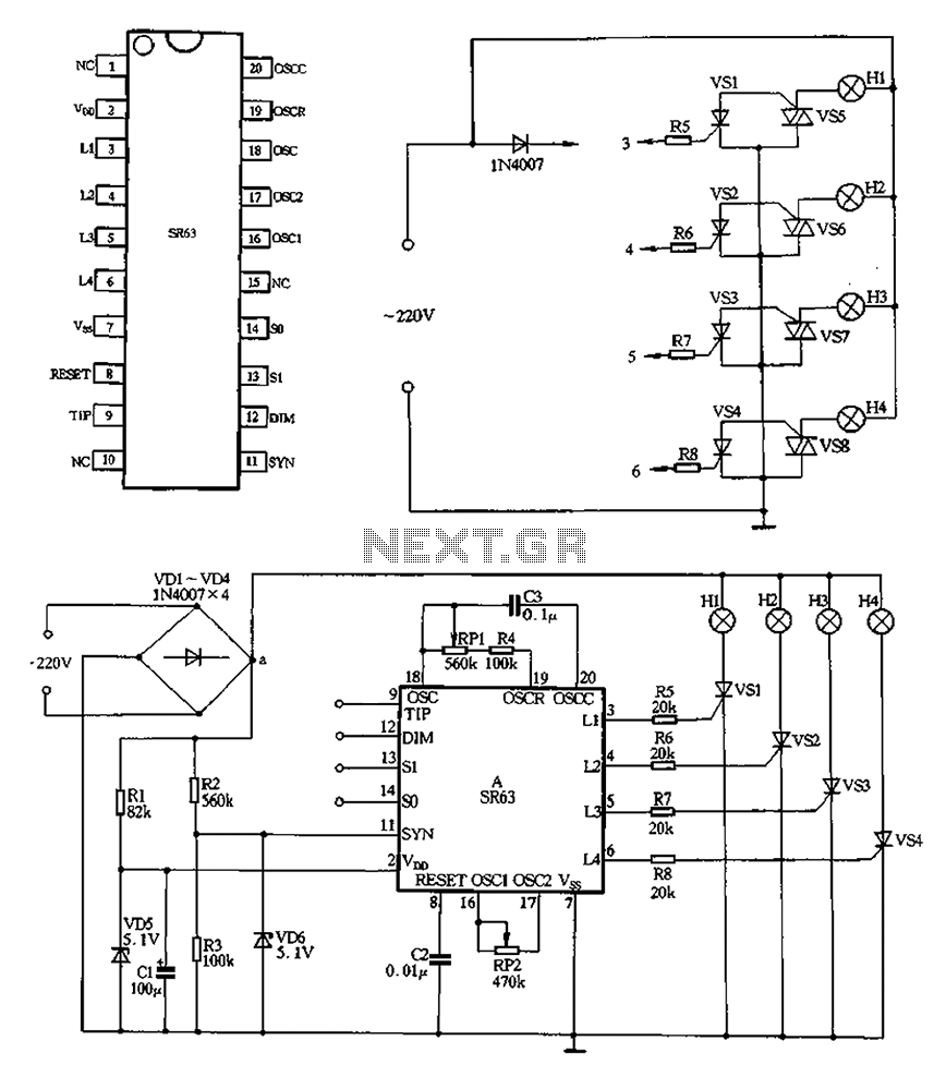
Description: 220V AC is converted to DC after passing through a VDI ~ VD4 bridge rectifier. The output from one point supplies power directly to lights H1 through H4. Another route passes through R1, a buck converter, and VD5, which regulates the output to approximately 5V DC. The voltage supply manifold A is supported by a voltage divider formed by R2 and R3, which provides a synchronization signal for manifold A. Components RP1, R4, C3, and SR63 are part of the oscillator circuit system, where adjusting the value of RP1 can change the oscillation frequency, affecting the chase speed of the four lights. RP2 is incorporated into the dimming oscillator circuit; adjusting RP2 alters the speed and brightness contrast of the lights. The circuit also includes a control terminal for four lights, which should be connected to a switch or a switching operation as needed, as referenced in table 2-41.
The circuit described operates by first converting an AC voltage of 220V to a DC voltage using a bridge rectifier formed by diodes VD1 to VD4. The output is then utilized to power four lights (H1 to H4) directly, ensuring reliable illumination. Additionally, a secondary pathway involves a buck converter (R1) and a voltage regulator (VD5) to step down the voltage to approximately 5V DC, which is essential for powering low-voltage components within the circuit.
The voltage divider composed of resistors R2 and R3 serves a dual purpose: it not only stabilizes the voltage supply to manifold A but also generates a synchronization signal that is critical for the timing functions of the circuit. The oscillator circuit, which includes RP1, R4, C3, and SR63, is designed to produce a variable frequency output. By adjusting RP1, the frequency of oscillation can be modified, which in turn influences the chase speed of the lights, allowing for dynamic visual effects.
Furthermore, RP2 is integrated into the dimming oscillator circuit, providing the capability to adjust the brightness of the lights. The adjustment of RP2 affects both the speed and the contrast of the light output, enabling a range of visual presentations from bright to dim settings.
The control terminals for the four lights can be connected to a switch or configured for a specific operation mode, as indicated in the referenced table 2-41. This flexibility allows for the customization of the lighting effects based on user requirements or specific application scenarios, making this circuit suitable for various lighting control applications.220V AC after VDI ~ VD4 bridge rectifier, the output of a point, all the way to direct electricity for lights H1 ~ H4; another way through Rl buck, VD5 regulator, about 5v DC o utput voltage, the electricity supply manifold A. R2, R3 form a voltage divider provides a synchronization signal for the manifold A. RP1, R4, C3 and SR63 within the oscillator circuit system, adjust the value of the RPI system can change the oscillation frequency rate, muscle and can be adjusted four lights chase speed. RP2 inner circuit dimming oscillator circuit, the adjustment value of RP2 can change the speed and dimming lights bright and dark contrast.
FIG DIM, Sl, so, TIP missed four control terminal t in the actual production should be connected with a switch or a switching operation according to the pattern need to refer to table 2-41.
The circuit described operates by first converting an AC voltage of 220V to a DC voltage using a bridge rectifier formed by diodes VD1 to VD4. The output is then utilized to power four lights (H1 to H4) directly, ensuring reliable illumination. Additionally, a secondary pathway involves a buck converter (R1) and a voltage regulator (VD5) to step down the voltage to approximately 5V DC, which is essential for powering low-voltage components within the circuit.
The voltage divider composed of resistors R2 and R3 serves a dual purpose: it not only stabilizes the voltage supply to manifold A but also generates a synchronization signal that is critical for the timing functions of the circuit. The oscillator circuit, which includes RP1, R4, C3, and SR63, is designed to produce a variable frequency output. By adjusting RP1, the frequency of oscillation can be modified, which in turn influences the chase speed of the lights, allowing for dynamic visual effects.
Furthermore, RP2 is integrated into the dimming oscillator circuit, providing the capability to adjust the brightness of the lights. The adjustment of RP2 affects both the speed and the contrast of the light output, enabling a range of visual presentations from bright to dim settings.
The control terminals for the four lights can be connected to a switch or configured for a specific operation mode, as indicated in the referenced table 2-41. This flexibility allows for the customization of the lighting effects based on user requirements or specific application scenarios, making this circuit suitable for various lighting control applications.220V AC after VDI ~ VD4 bridge rectifier, the output of a point, all the way to direct electricity for lights H1 ~ H4; another way through Rl buck, VD5 regulator, about 5v DC o utput voltage, the electricity supply manifold A. R2, R3 form a voltage divider provides a synchronization signal for the manifold A. RP1, R4, C3 and SR63 within the oscillator circuit system, adjust the value of the RPI system can change the oscillation frequency rate, muscle and can be adjusted four lights chase speed. RP2 inner circuit dimming oscillator circuit, the adjustment value of RP2 can change the speed and dimming lights bright and dark contrast.
FIG DIM, Sl, so, TIP missed four control terminal t in the actual production should be connected with a switch or a switching operation according to the pattern need to refer to table 2-41.
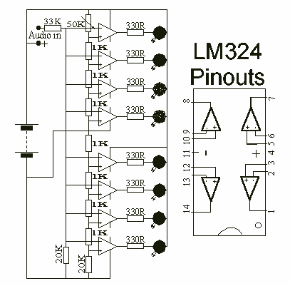
8 LED`s Audio VU Meter
This circuit uses two quad op-amps to form an eight LED audio level meter. The op-amp used in this particular circuit is the LM324. It is a popular IC and should be available from many parts stores. The 1K resistors...
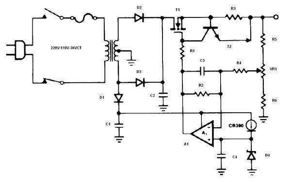
Battery charger or Power Supply 14 volt 4 ampere
The schematic diagram originates from a circuit designed as a battery charger/power supply with an output of 14V and a maximum current of 4A, utilizing the VN64GA MOSFET. This high-performance battery charger is specifically engineered for gelled electrolyte lead-acid batteries,...
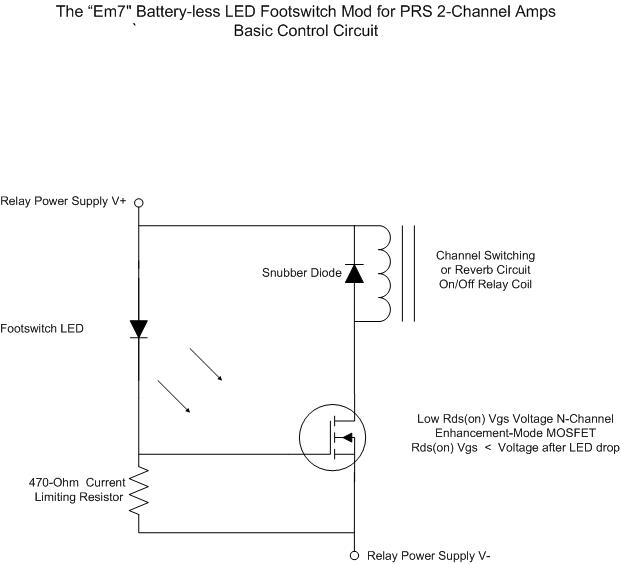
Battery less LED Footswitch Mod for the 2 Channels
For individuals seeking LED-based footswitching without the inconvenience of battery installation, a battery-less LED-based footswitch modification is being developed for 2-channel amplifiers. This solution is designed to work with the existing TRS jack and footswitch, and it will involve a...
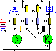
Two Flashing LEDs Circuit
This circuit diagram illustrates a setup for two flashing LEDs designed for various applications, including model construction and recreational uses. It features adjustable flashing speeds controlled by two potentiometers. The circuit comprises a combination of active and passive components. It...
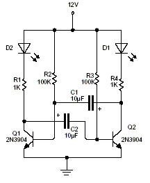
2 LED Flasher
This is a 2 LED flashing circuit. It is based on an analog flip flop circuit. This particular circuit was calculated to use blue or white 3V LED with a 12V power supply. If you are using red green or...
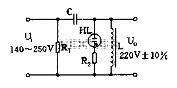
Easy exchange of magnetic saturation voltage regulator circuit
Easy exchange of magnetic saturation voltage regulator circuit
The magnetic saturation voltage regulator circuit is designed to stabilize output voltage levels by utilizing magnetic saturation principles. This circuit typically employs a magnetic core, which operates in saturation to regulate voltage,...
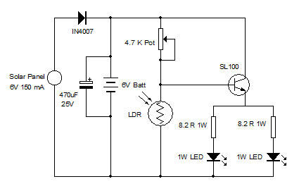
White LED Lamp with Solar Panel
In various industrial processes, it is essential to rotate a DC (or AC) motor both forward and reverse for a specified duration. Initially, the motor rotates forward (clockwise) for a certain period (approximately 2 to 3 minutes), then stops for...
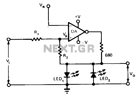
Visual-level-indicator
This indicator functions as a switch with hysteresis characteristics. When the input voltage temporarily or permanently exceeds the highest reference level, LED1 is activated. Conversely, if the voltage drops below the lowest reference level, LED1 turns off and LED2 is...
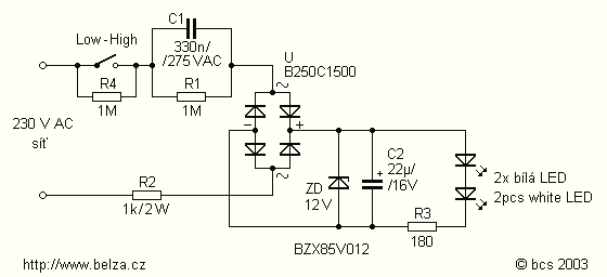
220 V LED Night light
This is a capacitor power supply. This is a very small current of energy-effective because it has very little loss, much smaller than the miniature transformer. Capacitor impedance is inversely proportional to frequency. This is a great disadvantage when the...