


Stairs Corridor light-controlled circuit
#field effect tube
#self-lighting
#controller
#corridor light
#automatic control
#electronic components
#energy saving
#home automation
#sensor
#low power
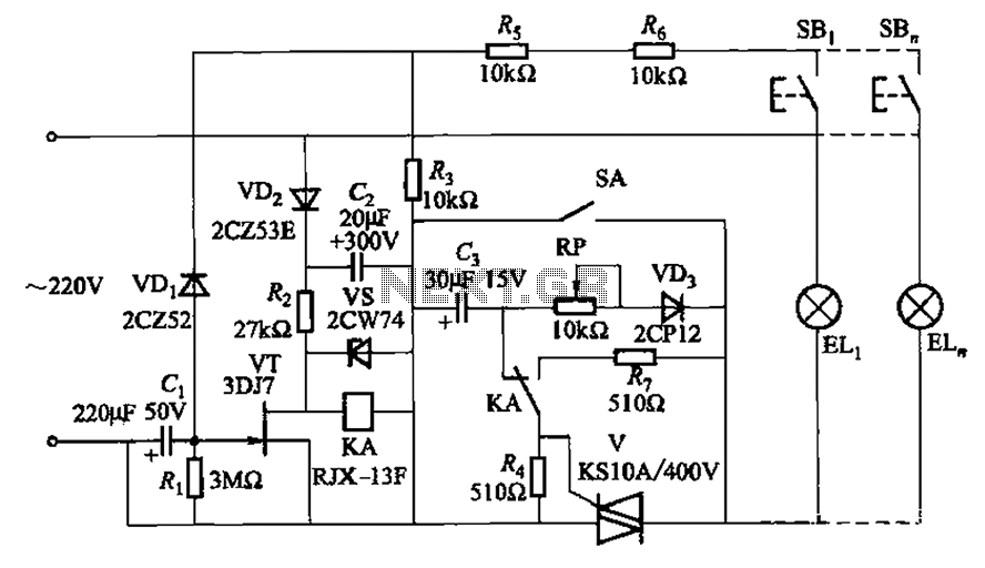
Description: The circuit illustrated in Figure 2-50 utilizes a field effect tube and a combination of electronic components to create a unique self-lighting controller. The working lamp remains illuminated at a reduced brightness rather than being completely turned off, which can be beneficial in certain situations. This method also significantly prolongs the lifespan of the lamps, as the filament initially operates at a cooler state with higher resistance, thereby preventing a surge of current when the lamp is connected to the power grid. The delay time for the circuit is determined by the capacitor (Ci) and resistor (Ri), which is approximately 6 minutes as indicated in Figure 2-50. To disconnect the controller and enhance the lighting, for instance, during stair cleaning, the switch (SA) can be toggled to the closed position, allowing the lamp to receive full grid voltage.
The circuit design employs a field effect transistor (FET) as the primary switching element, which is known for its high input impedance and low power consumption. The self-lighting controller operates by gradually increasing the voltage across the lamp, thereby reducing the inrush current that typically occurs when a lamp is turned on. This gradual increase in brightness not only enhances user comfort but also minimizes thermal stress on the filament, leading to a longer operational life for incandescent bulbs.
The delay mechanism is essential for applications where a constant low-level illumination is desired, such as in hallways or staircases. The time constant, governed by the values of the capacitor (Ci) and resistor (Ri), can be adjusted to suit specific requirements. By selecting different component values, the delay time can be modified, allowing for customization based on the intended use of the lighting system.
In practical applications, the circuit can be integrated into various lighting fixtures, providing automatic dimming capabilities. The switch (SA) serves as a manual override, enabling users to bypass the dimming function and access full brightness when necessary. This feature is particularly useful during cleaning or maintenance tasks, ensuring safety and visibility.
Overall, this self-lighting controller circuit represents an innovative approach to lighting management, combining efficiency with user-friendly operation. Its design principles can be adapted for a wide range of lighting applications, making it a versatile solution in modern electrical engineering. Circuit shown in Figure 2-50. This circuit uses field effect tube should, through the ingenious electronic components constitute a unique self-lighting controller. The informal working lamp illumination is not put out off, but the light is dim. In some cases this is needed. At the same time, this can greatly extend the life of lamps, because before fully lighting the lamp filament has a large cooler state filament resistance, thus avoiding that a large electric lamp connected to the grid when the impact of flow. Delay time is determined by Ci, Ri, as shown by numerical Figure 2-50 about 6min. To disconnect from the controller and enhanced lighting, for example, when cleaning stairs, hit the switch SA may be closed position, then the lamp will add a full-grid voltage.
The circuit design employs a field effect transistor (FET) as the primary switching element, which is known for its high input impedance and low power consumption. The self-lighting controller operates by gradually increasing the voltage across the lamp, thereby reducing the inrush current that typically occurs when a lamp is turned on. This gradual increase in brightness not only enhances user comfort but also minimizes thermal stress on the filament, leading to a longer operational life for incandescent bulbs.
The delay mechanism is essential for applications where a constant low-level illumination is desired, such as in hallways or staircases. The time constant, governed by the values of the capacitor (Ci) and resistor (Ri), can be adjusted to suit specific requirements. By selecting different component values, the delay time can be modified, allowing for customization based on the intended use of the lighting system.
In practical applications, the circuit can be integrated into various lighting fixtures, providing automatic dimming capabilities. The switch (SA) serves as a manual override, enabling users to bypass the dimming function and access full brightness when necessary. This feature is particularly useful during cleaning or maintenance tasks, ensuring safety and visibility.
Overall, this self-lighting controller circuit represents an innovative approach to lighting management, combining efficiency with user-friendly operation. Its design principles can be adapted for a wide range of lighting applications, making it a versatile solution in modern electrical engineering. Circuit shown in Figure 2-50. This circuit uses field effect tube should, through the ingenious electronic components constitute a unique self-lighting controller. The informal working lamp illumination is not put out off, but the light is dim. In some cases this is needed. At the same time, this can greatly extend the life of lamps, because before fully lighting the lamp filament has a large cooler state filament resistance, thus avoiding that a large electric lamp connected to the grid when the impact of flow. Delay time is determined by Ci, Ri, as shown by numerical Figure 2-50 about 6min. To disconnect from the controller and enhanced lighting, for example, when cleaning stairs, hit the switch SA may be closed position, then the lamp will add a full-grid voltage.
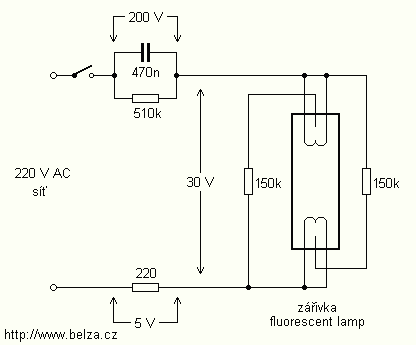
Energy Saving Night Light circuit
The lamps are usually used as ballast or electronic ballast inverter. Here it is used to reduce voltage capacitor reactance. Interesting is also the method of ignition of the auxiliary electrodes involved over 150 Ohm resistors. To start simply involve...

micro power pulse generator
This circuit generates clean logic pulses with minimal current consumption. It is designed to produce short 2 ms pulses at a frequency of one pulse per second, drawing only 1 microamp from a 9-volt battery.
The described circuit operates efficiently by...
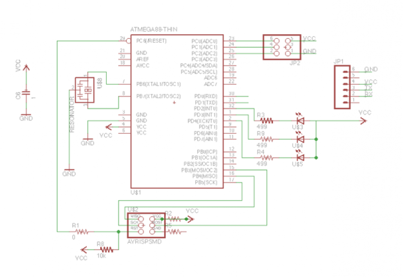
Add a sensor to a board and measure something with it
This week's plan is to build a device that warns of the potential for a knockdown, which is the process by which an over-canvassed ship is laid over on her beam-ends. The risk of sinking is high during this event,...
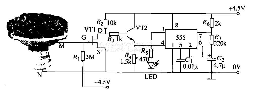
Pots water alarm circuit
The flowers in pots require watering, as relying solely on the observation of moist soil surfaces can be unreliable. To address this issue, a flower watering indicator has been developed. This circuit includes a field effect transistor (VT1), a second...
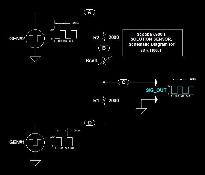
Scoobas Solution Sensing Tactic
This document serves multiple purposes, primarily to document the methods employed by a Scooba robot to detect: a) the presence of an acceptable cleaning solution being delivered to its pump, and b) the excess presence of used solution collected off...
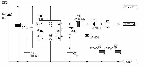
Low Power Negative Car Power Supply
I have had a lot of queries about getting a low power negative supply in cars, to power Linkwitz transform circuits and the like. There is a switchmode converter, but I must admit that it is overkill for what most...
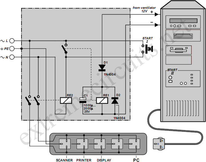
Automatic Mains Disconnect
Downloading and CD-burning programs often offer the option to automatically shut down the PC upon completion of their tasks. However, this energy-saving feature is ineffective if all peripheral equipment remains connected to the mains and continues to consume power even...
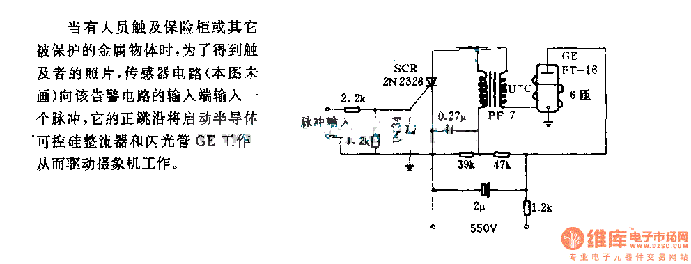
The alarm circuit diagram for safety box and other metal objects
When an individual touches the safety box or other protected metal objects, the sensor circuit generates a pulse to the alarm circuit. The positive edge of this pulse activates the semiconductor and thyristor flash GE, subsequently triggering the camera to...
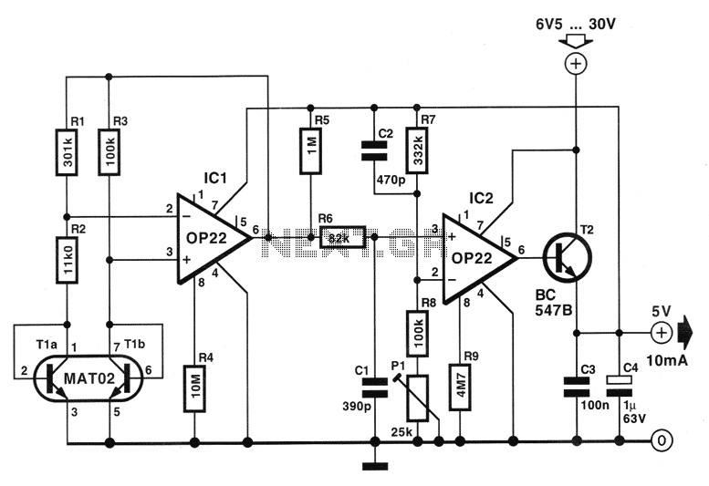
Low Power consumption 5V regulator circuit
The circuit described below is notable for its low power consumption. With a 9V input and no load at the output, it draws only 50 mA, which is significantly lower than the quiescent current of a 78L05 regulator. The circuit...