


Supply Voltage Indicator
#voltage indicator
#LED
#power supply monitor
#blinking LED
#voltage drop
#12V
#status indicator
#visual feedback
#simple circuit
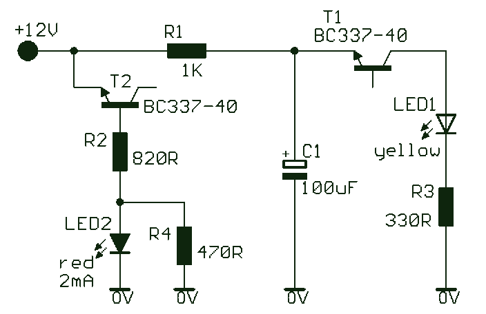
Description: A novel supply voltage monitor which uses a LED to show the status of a power supply. This simple and slightly odd circuit can clearly show the level of the supply voltage (in a larger device): as long as the indicator has good 12 volts at its input, LED1 gives steady, uninterrupted (for the naked eye) yellow light. If the input voltage falls below 11 V, LED1 will start to blink and the blinking will just get slower and slower if the voltage drops further - giving very clear and intuitive representation of the supply's status. The blinking will stop and LED1 will finally go out at a little below 9 volts. On the other hand, if the input voltage rises to 13 V, LED2 will start to glow, getting at almost full power at 14 V. The characteristic voltages can be adjusted primarily.
The described voltage monitor circuit is designed to provide visual feedback on the status of a power supply through the use of two LEDs, LED1 and LED2, each indicating different voltage thresholds. The circuit operates within a specified voltage range, monitoring input voltages from approximately 9 V to 14 V.
When the input voltage is at or above 12 V, LED1 emits a steady yellow light, indicating that the power supply is functioning within an acceptable range. As the voltage decreases below 11 V, LED1 begins to blink. The frequency of the blinking decreases progressively with further drops in voltage, providing an intuitive representation of the power supply's condition. This feature allows users to quickly assess the health of the power supply at a glance. Once the voltage drops below 9 V, LED1 extinguishes, signaling that the power supply is no longer operating within safe limits.
Conversely, when the input voltage exceeds 13 V, LED2 activates, emitting light that increases in intensity as the voltage approaches 14 V. This serves as an alert for over-voltage conditions. The design allows for user adjustments of the voltage thresholds, enabling customization based on specific application requirements.
The circuit likely employs voltage divider networks and comparator circuits to detect the voltage levels and control the LEDs accordingly. A microcontroller or an operational amplifier may be utilized to manage the blinking behavior of LED1, ensuring precise control over the frequency of the blinking as the voltage decreases.
In summary, this voltage monitor circuit is an effective tool for visually indicating both under-voltage and over-voltage conditions, enhancing the reliability and safety of electronic devices by providing clear and immediate feedback on the power supply status.A novel supply voltage monitor which uses a LED to show the status of a power supply. This simple and slightly odd circuit can clearly show the level of the supply voltage (in a larger device): as long as the indicator has good 12 volts at its input, LED1 gives steady, uninterrupted (for the naked eye) yellow light. If the input voltage falls below 11 V, LED1 will start to blink and the blinking will just get slower and slower if the voltage drops further - giving very clear and intuitive representation of the supply`s status.
The blinking will stop and LED1 will finally go out at a little below 9 volts. On the other hand, if the input voltage rises to 13 V, LED2 will start to glow, getting at almost full power at 14 V. The characteristic voltages can be adjusted primaril
The described voltage monitor circuit is designed to provide visual feedback on the status of a power supply through the use of two LEDs, LED1 and LED2, each indicating different voltage thresholds. The circuit operates within a specified voltage range, monitoring input voltages from approximately 9 V to 14 V.
When the input voltage is at or above 12 V, LED1 emits a steady yellow light, indicating that the power supply is functioning within an acceptable range. As the voltage decreases below 11 V, LED1 begins to blink. The frequency of the blinking decreases progressively with further drops in voltage, providing an intuitive representation of the power supply's condition. This feature allows users to quickly assess the health of the power supply at a glance. Once the voltage drops below 9 V, LED1 extinguishes, signaling that the power supply is no longer operating within safe limits.
Conversely, when the input voltage exceeds 13 V, LED2 activates, emitting light that increases in intensity as the voltage approaches 14 V. This serves as an alert for over-voltage conditions. The design allows for user adjustments of the voltage thresholds, enabling customization based on specific application requirements.
The circuit likely employs voltage divider networks and comparator circuits to detect the voltage levels and control the LEDs accordingly. A microcontroller or an operational amplifier may be utilized to manage the blinking behavior of LED1, ensuring precise control over the frequency of the blinking as the voltage decreases.
In summary, this voltage monitor circuit is an effective tool for visually indicating both under-voltage and over-voltage conditions, enhancing the reliability and safety of electronic devices by providing clear and immediate feedback on the power supply status.A novel supply voltage monitor which uses a LED to show the status of a power supply. This simple and slightly odd circuit can clearly show the level of the supply voltage (in a larger device): as long as the indicator has good 12 volts at its input, LED1 gives steady, uninterrupted (for the naked eye) yellow light. If the input voltage falls below 11 V, LED1 will start to blink and the blinking will just get slower and slower if the voltage drops further - giving very clear and intuitive representation of the supply`s status.
The blinking will stop and LED1 will finally go out at a little below 9 volts. On the other hand, if the input voltage rises to 13 V, LED2 will start to glow, getting at almost full power at 14 V. The characteristic voltages can be adjusted primaril
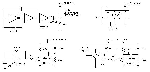
1 5 volt led flashers
The LED flasher circuits operate on a single 1.5-volt battery. The circuit on the upper right utilizes the widely used LM3909 LED flasher integrated circuit (IC) and requires only a timing capacitor and an LED.
The LM3909 is a specialized integrated...
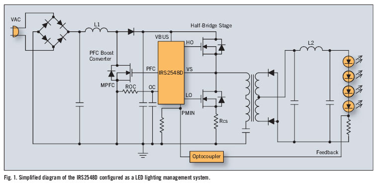
led lighting management ic improves power factor and efficiency
There is significant sensitivity to operating costs when managing high-powered commercial lighting. In these applications, there is a heightened focus on energy efficiency and AC line power factor, as these parameters influence operating expenses. Electric utilities impose additional charges on...
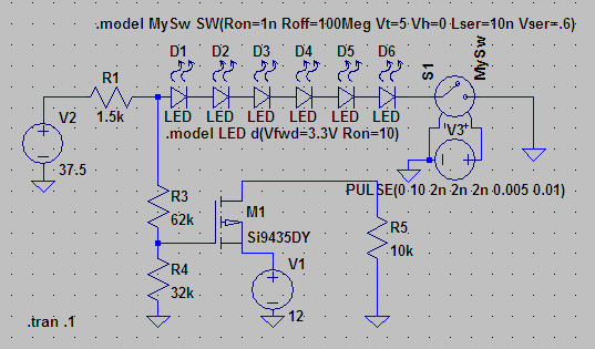
switch mode power supply design of current load sense circuit
A suitable method to sense when some LEDs in a garage door opener are illuminated. A power source, potentially the same as Vout, connects to a 1.5 kΩ resistor, which then connects to six LEDs followed by a transistor. This...
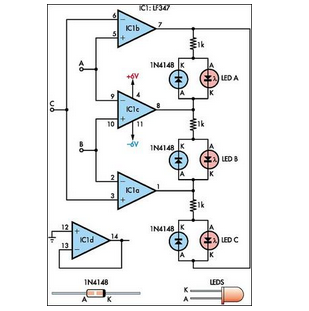
Maximum Minimum Voltage Indicator
This circuit indicates which of three voltages in the range from approximately -4V to +4V at points A, B, and C is the highest by illuminating one of three indicators.
The circuit is designed to compare three input voltages, labeled A,...
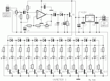
12 led vu meter circuit
This circuit provides a simple visual indication of audio level signals, adaptable to various user requirements. It can be configured for different input levels, which can be adjusted using trimmer potentiometers TR1 (state) and TR2 (gain). The audio signals are...
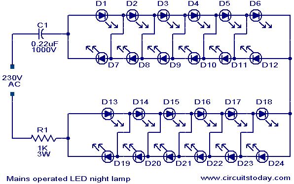
Mains operated LED night lamp
A simple and effective LED-based night lamp circuit is designed to operate directly from the 230V mains supply. The circuit utilizes a total of 24 white LEDs, producing an output of approximately 15W. Current limiting is achieved through resistor R1...
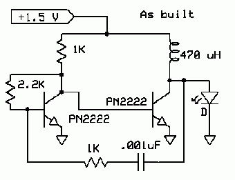
LED Boost Circuit
The completed board may be driven by voltages between 0.8 and 3 Volts. While the basic design goal was candle-like light from a single cell, the values used were chosen to allow safe operation from 3 Volts so you can,...
Led flasher
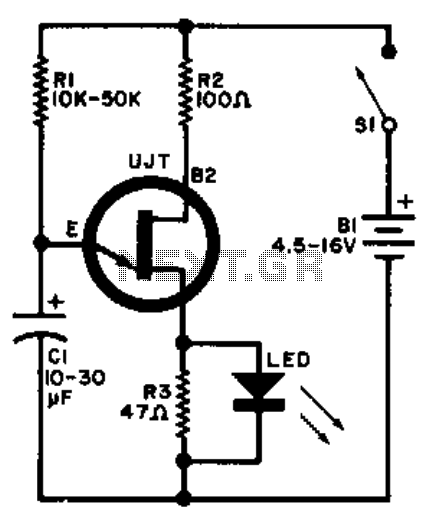
A relaxation oscillator is employed to flash an LED in the base circuit. The capacitor C1 is charged slowly through resistor R1 by the power source, and then it is discharged periodically through resistor R3 and the LED by the...
Fairy Flashing LED Lights
This simple and inexpensive circuit is not limited to Christmas use. It consists of two resistors, a small-signal transistor such as a BC547, and a flashing LED.
The circuit operates by utilizing a small-signal transistor, which acts as a switch to...