


the modern firepower pinball project
#LED-Wiz
#pinball
#solenoids
#driver board
#Williams WPC89
#Rottendog Amusements
#control circuit
#gaming
#electronics
#automation
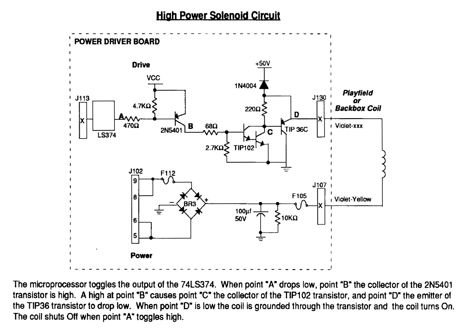
Description: Instructions for using an LED-Wiz to control pinball solenoids. Rottendog Amusements manufactures modern replacement driver boards, such as the Williams WPC89/WPC-S replacement. Although this board is an improvement over the originals, it remains relatively large and is capable of managing more than just solenoids. A critical component in a pinball machine is the control circuit that supplies power to the solenoids, which activate various mechanical assemblies like flippers, slingshots, and pop bumpers. These solenoids require substantial power to effectively move the heavy steel balls across the playfield. The Modern Firepower design operates at 50 volts, similar to the Williams machines of the past (not all pinball machines use or need 50 volts for their solenoids). Testing has shown that some solenoids can draw over 3 Amps of current when activated, resulting in more than 150 watts of power at 50 volts. This level of current can be dangerous, highlighting the importance of safe design and handling, as it surpasses the electrical handling capabilities of computers and standard control circuits. The solution lies in a power driver circuit board that serves as a bridge. This power driver must manage the high voltage and current flowing to the solenoids while also responding to low-powered control signals from the computing device, isolating it from the solenoid power. In pinball machines, this board is commonly known as the Solenoid Power Driver, often integrated with other circuits on larger circuit boards. For Modern Firepower, the control signal is transmitted from a PC to an LED-Wiz via USB, which then communicates with the Solenoid Power Driver to supply power to the various solenoids on the playfield. The 50-volt power is sourced from a separate power supply transformer that connects directly to the Solenoid Power Driver board. The Williams High Power Solenoid Circuit Schematic indicates that 50 volts flows directly to the playfield coil (activating the coil) and from the coil to a TIP36C PNP transistor. A TIP102 NPN transistor is utilized to connect the TIP36C to the 2N5401 PNP transistor.
The LED-Wiz is a USB-based controller designed for managing solenoids in pinball machines, allowing for precise control over various mechanical functions. The integration of the LED-Wiz with the Solenoid Power Driver is crucial for the operation of pinball machines, particularly in systems like Modern Firepower. The architecture of the circuit ensures that the high voltage required for solenoid operation does not interfere with the low voltage control signals from the LED-Wiz.
The Solenoid Power Driver board typically includes components such as transistors, diodes, and capacitors to manage the high power demands of the solenoids. The TIP36C PNP transistor plays a significant role in switching the high voltage to the solenoid coils, while the TIP102 NPN transistor acts as an intermediary, allowing the control signals from the LED-Wiz to activate the TIP36C without direct exposure to the high voltage. The 2N5401 PNP transistor may be used for additional switching or amplification, ensuring that the control signals are robust enough to handle the demands of the solenoids.
Furthermore, safety precautions must be taken when designing and implementing these circuits. Proper insulation, heat dissipation mechanisms, and circuit protection elements such as fuses or circuit breakers are essential to prevent accidents and ensure reliable operation. The power supply transformer must also be rated appropriately to handle the total load of the solenoids, with consideration for inrush currents that may occur during activation.
In summary, the combination of an LED-Wiz and a Solenoid Power Driver board enables effective control of pinball solenoids, facilitating the dynamic operation of mechanical assemblies in pinball machines while maintaining safety and reliability through proper circuit design and component selection.How to get an LED-Wiz to control pinball solenoids. Rottendog Amusements makes modern replacement Driver Boards like this Williams WPC89/WPC-S replacement. While it is better than the originals, this board is still rather large, though it does handle more than just solenoids.
One of the most important components in a pinball machine is the control circuit that sends power to the solenoids, moving the various mechanical assemblies like flippers, slingshots, and pop bumpers. The solenoids need lots of power to have enough oomph to move those heavy steel balls around the playfield.
The Modern Firepower design will be using 50 volts, just like the Williams machines back in the day (not all pinball machine designs use or require 50v for the solenoids). In testing, I`ve measured some solenoids to be pulling more than 3 Amps of current when they fire, and at 50 volts that`s over 150 watts of power!
This is enough current to be deadly to humans, so safe design and handling is essential, and this amount of power far exceeds the electricity handling capability of computers and typical control circuits. The solution is a power driver circuit board that bridges the gap. On one hand the power driver has to be capable of controlling the high voltage and amperage that is flowing to the solenoids, and on the other hand it has to respond to low powered control signals from the computing device while isolating it from the solenoid power.
In pinball machines, this circuit board is typically referred to as the Solenoid Power Driver, and often it is integrated onto larger circuit boards with other types of circuits. For Modern Firepower, the control signal will flow from a PC to a LED-Wiz over USB, then on to the Solenoid Power Driver sending power to the various solenoids on the playfield.
The 50v power comes from a separate power supply transformer which will feed directly to the Solenoid Power Driver board. Williams High Power Solenoid Circuit Schematic. 50v power flows directly to playfield coil (making the coil live) and from the coil to a TIP36C PNP transistor.
A TIP102 NPN transistor is used to connect the TIP36C to the 2N5401 PNP pr
The LED-Wiz is a USB-based controller designed for managing solenoids in pinball machines, allowing for precise control over various mechanical functions. The integration of the LED-Wiz with the Solenoid Power Driver is crucial for the operation of pinball machines, particularly in systems like Modern Firepower. The architecture of the circuit ensures that the high voltage required for solenoid operation does not interfere with the low voltage control signals from the LED-Wiz.
The Solenoid Power Driver board typically includes components such as transistors, diodes, and capacitors to manage the high power demands of the solenoids. The TIP36C PNP transistor plays a significant role in switching the high voltage to the solenoid coils, while the TIP102 NPN transistor acts as an intermediary, allowing the control signals from the LED-Wiz to activate the TIP36C without direct exposure to the high voltage. The 2N5401 PNP transistor may be used for additional switching or amplification, ensuring that the control signals are robust enough to handle the demands of the solenoids.
Furthermore, safety precautions must be taken when designing and implementing these circuits. Proper insulation, heat dissipation mechanisms, and circuit protection elements such as fuses or circuit breakers are essential to prevent accidents and ensure reliable operation. The power supply transformer must also be rated appropriately to handle the total load of the solenoids, with consideration for inrush currents that may occur during activation.
In summary, the combination of an LED-Wiz and a Solenoid Power Driver board enables effective control of pinball solenoids, facilitating the dynamic operation of mechanical assemblies in pinball machines while maintaining safety and reliability through proper circuit design and component selection.How to get an LED-Wiz to control pinball solenoids. Rottendog Amusements makes modern replacement Driver Boards like this Williams WPC89/WPC-S replacement. While it is better than the originals, this board is still rather large, though it does handle more than just solenoids.
One of the most important components in a pinball machine is the control circuit that sends power to the solenoids, moving the various mechanical assemblies like flippers, slingshots, and pop bumpers. The solenoids need lots of power to have enough oomph to move those heavy steel balls around the playfield.
The Modern Firepower design will be using 50 volts, just like the Williams machines back in the day (not all pinball machine designs use or require 50v for the solenoids). In testing, I`ve measured some solenoids to be pulling more than 3 Amps of current when they fire, and at 50 volts that`s over 150 watts of power!
This is enough current to be deadly to humans, so safe design and handling is essential, and this amount of power far exceeds the electricity handling capability of computers and typical control circuits. The solution is a power driver circuit board that bridges the gap. On one hand the power driver has to be capable of controlling the high voltage and amperage that is flowing to the solenoids, and on the other hand it has to respond to low powered control signals from the computing device while isolating it from the solenoid power.
In pinball machines, this circuit board is typically referred to as the Solenoid Power Driver, and often it is integrated onto larger circuit boards with other types of circuits. For Modern Firepower, the control signal will flow from a PC to a LED-Wiz over USB, then on to the Solenoid Power Driver sending power to the various solenoids on the playfield.
The 50v power comes from a separate power supply transformer which will feed directly to the Solenoid Power Driver board. Williams High Power Solenoid Circuit Schematic. 50v power flows directly to playfield coil (making the coil live) and from the coil to a TIP36C PNP transistor.
A TIP102 NPN transistor is used to connect the TIP36C to the 2N5401 PNP pr

Objects in Flux
The Open Source Automation project is a free automation software that operates on Windows and does not require programming for setup. It features a user-friendly graphical interface and includes unique functionalities that are not typically found in high-end security and...
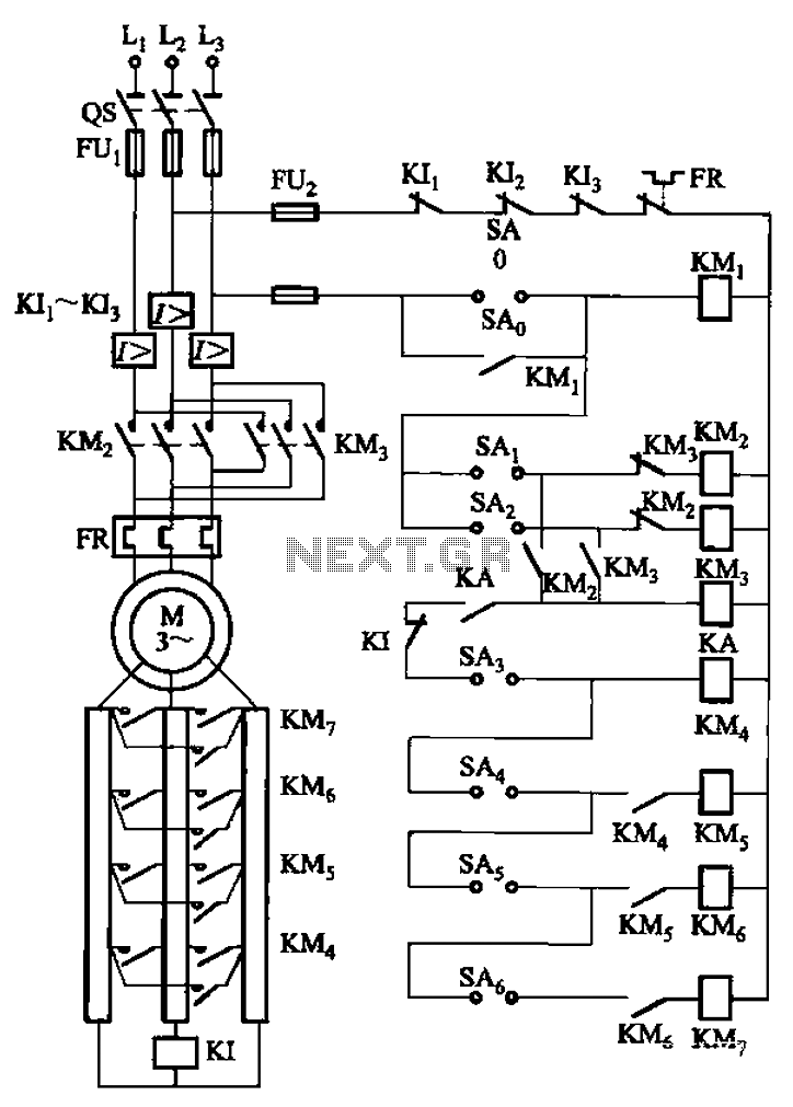
A control circuit reversing braking and reverse grading speed control function
The circuit depicted in Figure 3-168 utilizes a controller for speed grading and reversing control. A reverse brake is connected to the rotor circuit through an overcurrent relay, labeled KI, for control. The current relay KIi to KI3 serves as...
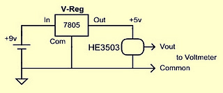
Pinball MAGNETISM circuits
It was observed that balls were becoming lodged in the ball trough, failing to load into an upkicker or not resting correctly on the trough ball microswitches or optos, which caused the machine to register a missing ball. Initially, there...
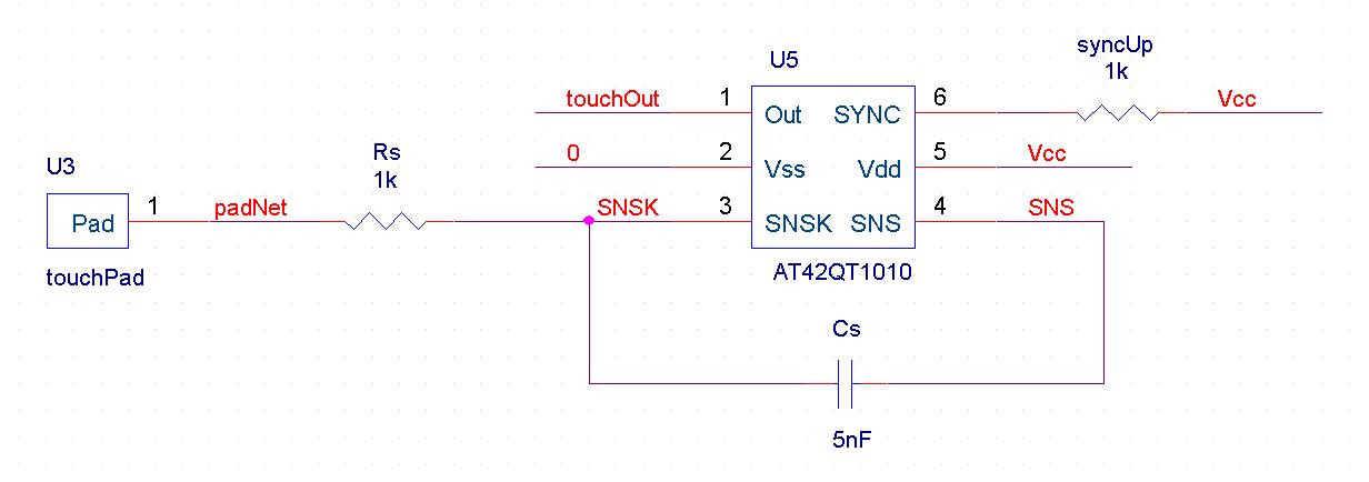
automatic pet feeder
An automatic feeder dispenses food based on the activation of a series of buttons, which interface with a system controller and a food dispenser. The system is designed for intelligent processing of inputs and outputs, allowing dynamic configuration of button...
Electronics Projects Circuits
Over 1400 top electronics projects and electronic circuits with photos, datasheets, and easy-to-read schematics, along with explanations of how they work and how to build them.
The collection comprises a vast array of electronics projects suitable for enthusiasts and professionals alike....
Coop automatic controller circuit diagram
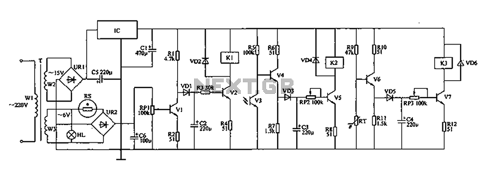
The automatic controller for a chicken coop is designed to automatically regulate light, temperature, and humidity, thereby enhancing egg production and survival rates of chickens. This device is intended for specialized poultry households in rural areas. The circuit operates through...