


The Super Capacitor Flashlight with Custom Charger and Voltage Booster
#super capacitor
#flashlight
#voltage booster
#custom charger
#wall transformer
#energy storage
#LED
#portable lighting
#power management
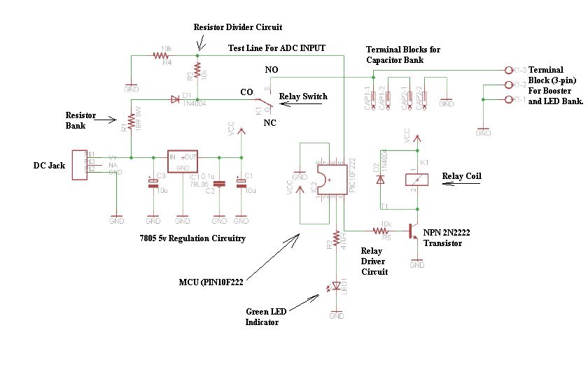
Description: The schematic consists of four hardware blocks: 1) The wall transformer 2) The charging circuit 3) The control unit 4) The output stage.
The circuit schematic is structured around four essential hardware blocks that facilitate the overall functionality of the system.
1. **Wall Transformer**: This block serves as the primary power source, converting the high-voltage AC from the mains supply into a lower voltage AC suitable for the circuit's requirements. Typically, a step-down transformer is employed to achieve the desired voltage levels, ensuring safe operation of subsequent components.
2. **Charging Circuit**: The charging circuit is responsible for converting the AC voltage from the wall transformer into a stable DC voltage. This is usually accomplished using a rectifier (either full-wave or half-wave) followed by a smoothing capacitor to filter out ripples, providing a steady DC output. This voltage is crucial for powering the control unit and other components effectively.
3. **Control Unit**: The control unit acts as the brain of the circuit, managing the operation of the entire system. It may incorporate a microcontroller or a dedicated logic circuit that processes input signals, executes programmed instructions, and controls the output stage based on predefined conditions. This block may also include various sensors and feedback mechanisms to monitor performance and adjust parameters dynamically.
4. **Output Stage**: The output stage is designed to deliver the final output of the circuit, whether it be a signal, power to another device, or any other form of output. This block may consist of amplifiers, drivers, or other components that ensure the output is at the required levels and formats for the intended application.
Each of these blocks is interconnected through a series of conductive paths, with careful attention paid to component ratings and specifications to ensure reliability and efficiency. The overall design must also consider aspects such as thermal management, electromagnetic compatibility, and safety standards to ensure optimal performance in real-world applications.Before I begin talking about the schematic, let it be known that there are four hardware blocks to this circuit: 1) The wall transformer 2) The charge..
The circuit schematic is structured around four essential hardware blocks that facilitate the overall functionality of the system.
1. **Wall Transformer**: This block serves as the primary power source, converting the high-voltage AC from the mains supply into a lower voltage AC suitable for the circuit's requirements. Typically, a step-down transformer is employed to achieve the desired voltage levels, ensuring safe operation of subsequent components.
2. **Charging Circuit**: The charging circuit is responsible for converting the AC voltage from the wall transformer into a stable DC voltage. This is usually accomplished using a rectifier (either full-wave or half-wave) followed by a smoothing capacitor to filter out ripples, providing a steady DC output. This voltage is crucial for powering the control unit and other components effectively.
3. **Control Unit**: The control unit acts as the brain of the circuit, managing the operation of the entire system. It may incorporate a microcontroller or a dedicated logic circuit that processes input signals, executes programmed instructions, and controls the output stage based on predefined conditions. This block may also include various sensors and feedback mechanisms to monitor performance and adjust parameters dynamically.
4. **Output Stage**: The output stage is designed to deliver the final output of the circuit, whether it be a signal, power to another device, or any other form of output. This block may consist of amplifiers, drivers, or other components that ensure the output is at the required levels and formats for the intended application.
Each of these blocks is interconnected through a series of conductive paths, with careful attention paid to component ratings and specifications to ensure reliability and efficiency. The overall design must also consider aspects such as thermal management, electromagnetic compatibility, and safety standards to ensure optimal performance in real-world applications.Before I begin talking about the schematic, let it be known that there are four hardware blocks to this circuit: 1) The wall transformer 2) The charge..

Two-LED Voltage Indicator
There are many applications where the accuracy of a digital or analog (bar graph) output is not necessary, but a solution that offers more than a simple low/high indicator is desirable.
In various electronic applications, there exists a need for indicators...
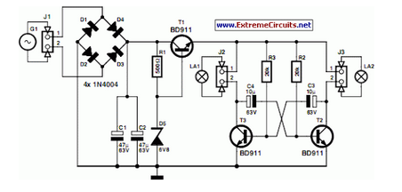
LED Bike Light Circuit Project
A front wheel with a built-in dynamo was purchased, providing a sine wave output of 30 Vpp at no load. Based on this, a simple power supply was designed using BD911 transistors, which are somewhat oversized for the application, but...
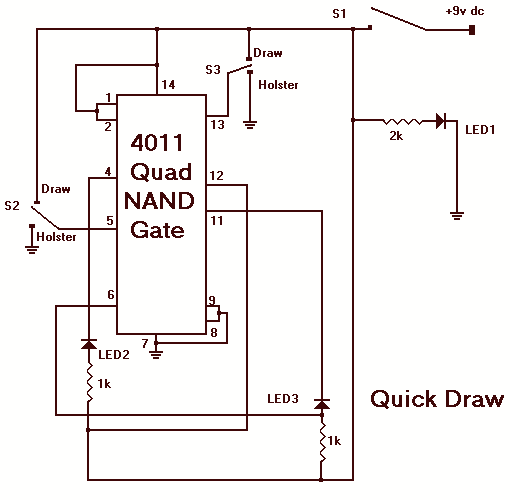
Quick move LED game
The object of Quick Draw is to test your reaction time against your opponent's. A third person acts as a referee and begins the duel by pressing S1, which lights LED1. Upon seeing LED1 go on, you try to outdraw...

LED Volt Meter
This circuit is a simple LED voltmeter designed to monitor the charge level of lead-acid or tubular batteries. The terminal voltage of the battery is displayed through four LED indicators. The nominal terminal voltage for a fully charged lead-acid battery...
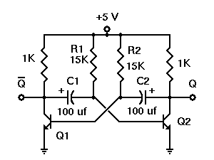
How does LED Flashes One by One in my Project Some Queries
A project called LED Flasher that sequentially flashes LEDs one by one. There is a query regarding the project, and any simple explanation would be greatly appreciated. A reference image or a link can be used for additional context.
The LED...

Scrchaser
Each lamp lights in succession to give the appearance of a growing column.
The described circuit features a sequential lighting system designed to illuminate a series of lamps in a cascading manner, creating the visual effect of a growing column of...
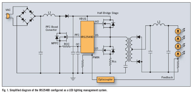
led lighting management ic improves power factor and efficiency
There is significant sensitivity to operating costs when managing high-powered commercial lighting. In these applications, there is a heightened focus on energy efficiency and AC line power factor, as these parameters influence operating expenses. Electric utilities impose additional charges on...
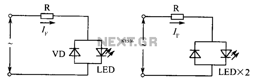
AC LED drive circuit
The circuit operates effectively even when the polarity of the voltage or the power supply is reversed. It functions with DC drives similar to AC drives, utilizing a current limiting resistor R. The value of this resistor is determined based...
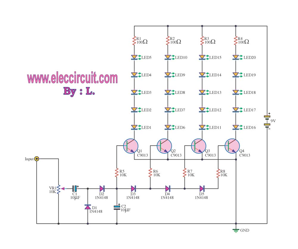
LED VU meter circuit by transistor
The VU meter operates in conjunction with the integrated amplifier circuit. The audio signal is processed by the audio amplifier circuit, which drives the VU meter to display the audio level.
The VU meter circuit is designed to visually represent the...