


Three-Way Touch Lamp
#touch lamp
#NE555
#timer
#three-way switch
#dimming
#pulse generator
#light control
#home automation
#electronic switch
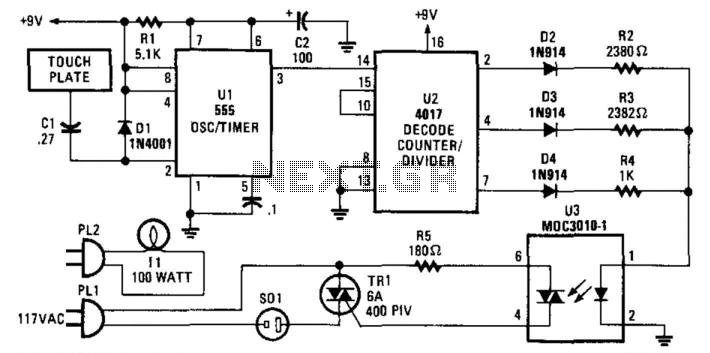
Description: A three-way switch controls a lamp with off-dim-bright settings using an NE555 timer to generate a one-second pulse, triggered by ambient AC fields detected by the human body. CI and D1 form an input network. U2 is a decode counter/divider that drives one of 10 outputs (three of which are utilized). The logic outputs control various resistors in series with the LED in the optocoupler. The optocoupler manages a triac that is in series with the load (lamp, etc.). By reconfiguring the outputs of U2, it is possible to achieve more than three brightness levels, up to a maximum of 10. An IN914 diode and a resistor are required for each output.
The circuit design utilizes a three-way switch to manage the brightness of a lamp, providing options for off, dim, and bright settings. The NE555 timer serves as the core component for generating a one-second pulse, which is essential for the operation of the system. This pulse is triggered by ambient AC fields detected by the human body, allowing for a touch-sensitive control mechanism that enhances user interaction with the lamp.
The input network is composed of a capacitor (CI) and a diode (D1), which work together to filter and condition the incoming signals from the ambient fields. The decoded output of the NE555 timer is fed into a decode counter/divider (U2), which is capable of producing up to 10 distinct outputs. In this application, three of these outputs are utilized to control the brightness levels of the lamp.
The logic outputs from U2 are connected to various resistors that are placed in series with an LED in an optocoupler. The optocoupler serves as an interface between the low-voltage control signals and the higher voltage required to drive the lamp. The output from the optocoupler controls a triac, which acts as a switch for the lamp load. The triac allows for smooth control of the lamp's brightness by regulating the power delivered to it.
To expand the functionality of the circuit, the outputs from U2 can be reconfigured, enabling the achievement of up to 10 different brightness levels. This flexibility allows for a wide range of lighting conditions to suit various user preferences. Each output requires an IN914 diode and a resistor to ensure proper operation and signal integrity. Overall, this circuit design exemplifies an innovative approach to lighting control, utilizing modern electronic components to create a versatile and user-friendly lighting solution. A three-way switch to control a lamp (off-dim-bright, etc.) uses an NE555 timer to generate a one-second pulse, trigge red by ambient ac fields that are picked up by the human body. CI and D1 form an input network. U2 is a decode counter/divider and drives one of 10 outputs (three are used). The logic outputs drive various resistors in series with the LED in the optocoupler. The optocoupler controls a triac that is in series with a load (lamp, etc.). By reconfiguring the outputs of U2, more than three brightness levels can be obtained, up to 10. An IN914 and resistor will be required for each output.
The circuit design utilizes a three-way switch to manage the brightness of a lamp, providing options for off, dim, and bright settings. The NE555 timer serves as the core component for generating a one-second pulse, which is essential for the operation of the system. This pulse is triggered by ambient AC fields detected by the human body, allowing for a touch-sensitive control mechanism that enhances user interaction with the lamp.
The input network is composed of a capacitor (CI) and a diode (D1), which work together to filter and condition the incoming signals from the ambient fields. The decoded output of the NE555 timer is fed into a decode counter/divider (U2), which is capable of producing up to 10 distinct outputs. In this application, three of these outputs are utilized to control the brightness levels of the lamp.
The logic outputs from U2 are connected to various resistors that are placed in series with an LED in an optocoupler. The optocoupler serves as an interface between the low-voltage control signals and the higher voltage required to drive the lamp. The output from the optocoupler controls a triac, which acts as a switch for the lamp load. The triac allows for smooth control of the lamp's brightness by regulating the power delivered to it.
To expand the functionality of the circuit, the outputs from U2 can be reconfigured, enabling the achievement of up to 10 different brightness levels. This flexibility allows for a wide range of lighting conditions to suit various user preferences. Each output requires an IN914 diode and a resistor to ensure proper operation and signal integrity. Overall, this circuit design exemplifies an innovative approach to lighting control, utilizing modern electronic components to create a versatile and user-friendly lighting solution. A three-way switch to control a lamp (off-dim-bright, etc.) uses an NE555 timer to generate a one-second pulse, trigge red by ambient ac fields that are picked up by the human body. CI and D1 form an input network. U2 is a decode counter/divider and drives one of 10 outputs (three are used). The logic outputs drive various resistors in series with the LED in the optocoupler. The optocoupler controls a triac that is in series with a load (lamp, etc.). By reconfiguring the outputs of U2, more than three brightness levels can be obtained, up to 10. An IN914 and resistor will be required for each output.
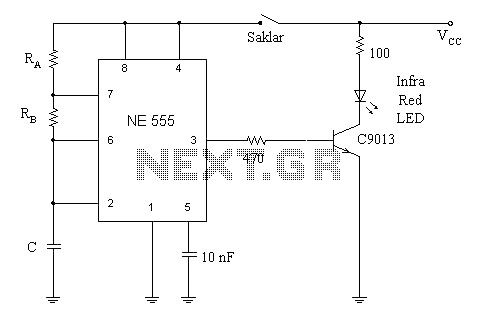
remote control using the ne 555 and lm 567
A simple circuit diagram illustrates a schematic for a remote control system, which consists of two components: a transmitter and a receiver. The transmitter circuit is controlled by the NE555 integrated circuit (IC). This system operates by detecting the emitted...
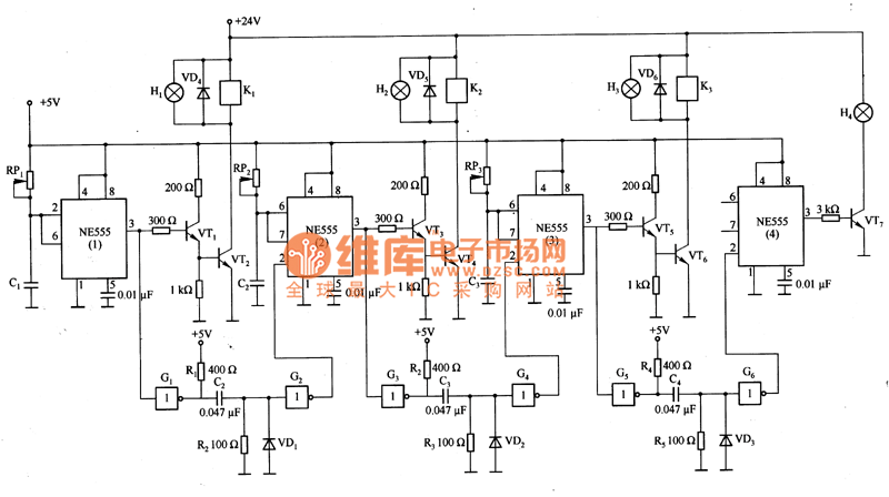
Sequence timer diagram composed by NE555
This is a sequence timer diagram composed of an NE555 timer. The timer can be set to any duration when the power is connected, allowing it to control an external system. In the circuit, K1-K3 are relays used to activate...
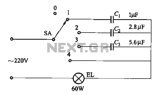
Dimming circuit using capacitance
A dimming circuit capacitor circuit is illustrated in Figure 2-63. When the switch SA is moved from position "1" to "3," the capacitance increases in ascending order, resulting in the light bulb brightness also increasing correspondingly. When SA is set...
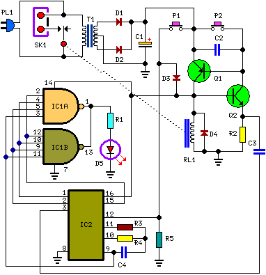
A Bedside Lamp Timer Circuit Schematic
The purpose of this circuit is to power a lamp or other appliance for a specified duration (30 minutes in this case) and then automatically turn it off. This functionality is particularly useful for reading in bed at night, as...
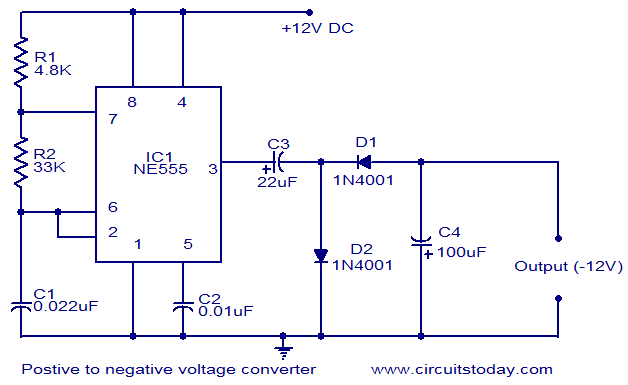
Positive voltage to negative voltage converter
This circuit diagram illustrates the method for obtaining a negative voltage from a positive voltage supply. An additional benefit of this circuit is that the negative voltage, combined with the original positive supply, can be used to simulate a dual...
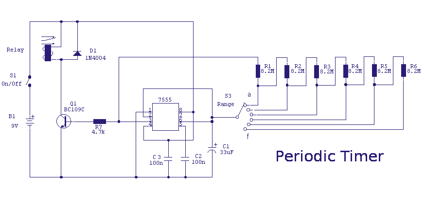
Periodic Timer
A switched timer with equal make and equal space periods timing adjustable from over 6 minutes to 38 minutes. This timer circuit is similar to the 5 to 30 minute timer except that when switch S1 is closed, the on/off...
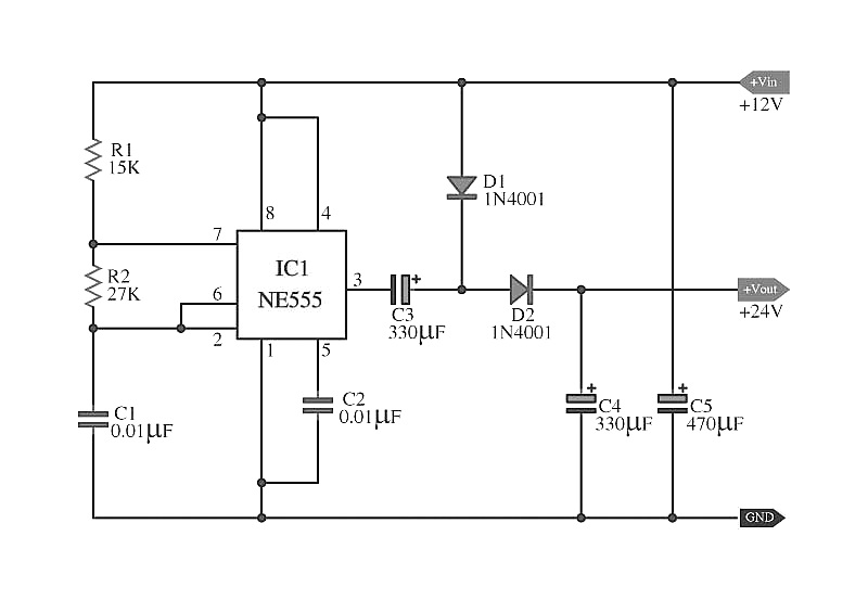
doubler voltage with ne555 schematic
The capacitors C5 work in conjunction with IC1, while the resistors R1 and R2, along with capacitors C1, form an astable multivibrator square wave generator. This generator outputs a frequency of approximately 2 kHz from pin 3 of IC1. Additionally,...
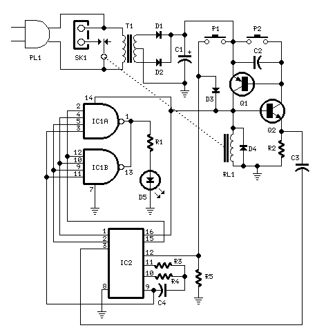
Bedside Lamp Timers
The objective of this circuit is to power a lamp or other device for a predetermined duration (30 minutes in this instance) and subsequently turn it off. This functionality is particularly beneficial for reading in bed at night, as it...
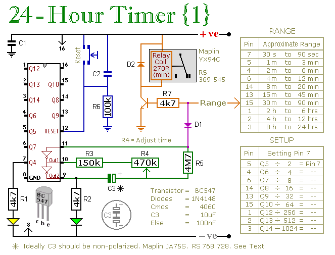
24 Hour Timer
These two circuits are multi-range timers that offer periods of up to 24 hours and beyond. Both circuits are fundamentally similar, with the key distinction being that Version 1 energizes the relay when the time expires, while Version 2 de-energizes...