


triac for this light dimmer circuit
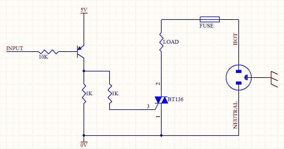
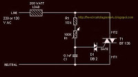
Description: A circuit was designed to function as a light dimmer, utilizing a BT136 SCR and an MOC3022 optocoupler. However, the circuit did not operate as intended.
The circuit aims to control the brightness of a light source through phase control using a silicon-controlled rectifier (SCR) and an optocoupler for isolation and triggering. The BT136 is a popular choice for light dimming applications due to its ability to handle significant power levels. It is a three-terminal device that requires a gate trigger to turn on and will remain on as long as the current through it exceeds a certain threshold.
The MOC3022 optocoupler plays a crucial role in providing electrical isolation between the control circuit and the high-voltage AC load. It consists of an LED and a phototransistor. When the LED is activated, it emits light that activates the phototransistor, allowing current to flow and triggering the gate of the BT136 SCR.
To ensure proper operation of the circuit, the following aspects should be examined:
1. **Component Ratings**: Verify that the BT136 and MOC3022 are rated for the voltage and current levels of the application. The SCR should be able to handle the peak voltage and current of the load.
2. **Triggering Circuit**: Ensure that the circuit designed to trigger the gate of the BT136 is functioning correctly. This may involve checking the resistor values, ensuring proper isolation, and confirming that the optocoupler is receiving adequate input.
3. **Phase Control Timing**: The timing of the triggering signal is critical for dimming functionality. The phase control method requires precise timing to adjust the point in the AC cycle at which the SCR is triggered, thus controlling the amount of power delivered to the load.
4. **Load Compatibility**: Confirm that the load (e.g., incandescent bulb) is compatible with dimming. Certain types of lights, such as LED or fluorescent bulbs, may require specific dimming circuits or additional components to function correctly.
By addressing these components and ensuring that all connections are secure and correctly configured, the circuit can be made operational. If issues persist, further troubleshooting may be necessary to identify any faulty components or design flaws.Hi all I made this circuit to be a light dimmer but it did not work. I use BT136 for the SCR and MOC3022 for optocoupler. Can you tell me what is the..
The circuit aims to control the brightness of a light source through phase control using a silicon-controlled rectifier (SCR) and an optocoupler for isolation and triggering. The BT136 is a popular choice for light dimming applications due to its ability to handle significant power levels. It is a three-terminal device that requires a gate trigger to turn on and will remain on as long as the current through it exceeds a certain threshold.
The MOC3022 optocoupler plays a crucial role in providing electrical isolation between the control circuit and the high-voltage AC load. It consists of an LED and a phototransistor. When the LED is activated, it emits light that activates the phototransistor, allowing current to flow and triggering the gate of the BT136 SCR.
To ensure proper operation of the circuit, the following aspects should be examined:
1. **Component Ratings**: Verify that the BT136 and MOC3022 are rated for the voltage and current levels of the application. The SCR should be able to handle the peak voltage and current of the load.
2. **Triggering Circuit**: Ensure that the circuit designed to trigger the gate of the BT136 is functioning correctly. This may involve checking the resistor values, ensuring proper isolation, and confirming that the optocoupler is receiving adequate input.
3. **Phase Control Timing**: The timing of the triggering signal is critical for dimming functionality. The phase control method requires precise timing to adjust the point in the AC cycle at which the SCR is triggered, thus controlling the amount of power delivered to the load.
4. **Load Compatibility**: Confirm that the load (e.g., incandescent bulb) is compatible with dimming. Certain types of lights, such as LED or fluorescent bulbs, may require specific dimming circuits or additional components to function correctly.
By addressing these components and ensuring that all connections are secure and correctly configured, the circuit can be made operational. If issues persist, further troubleshooting may be necessary to identify any faulty components or design flaws.Hi all I made this circuit to be a light dimmer but it did not work. I use BT136 for the SCR and MOC3022 for optocoupler. Can you tell me what is the..
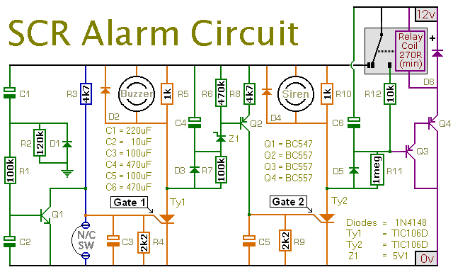
An SCR Based Burglar Alarm
This is a simple SCR-based burglar alarm circuit. Its features include automatic exit and entry delays, along with a timed bell cut-off and reset. It is designed to be used with the usual types of normally-closed input devices such as...
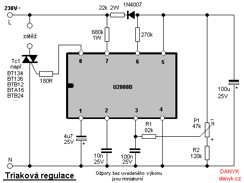
Triac regulation of mains voltage
Triac regulation is designed to control the power of mains appliances. It can adjust the brightness of incandescent light bulbs, halogen lamps, dimmable energy savers, heaters, and other thermal devices, as well as regulate motors. The power can be easily...
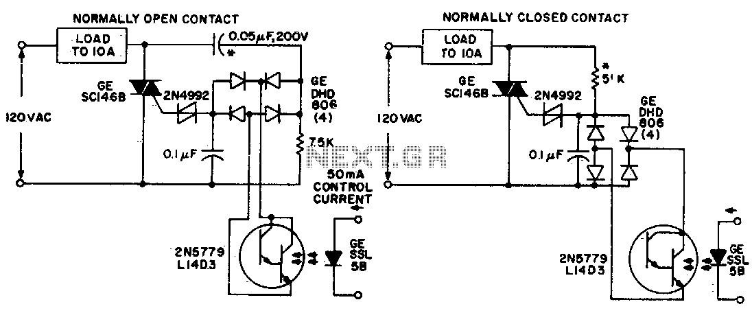
Light isolated solid state power relay circuits
Both circuits utilize the GE SC146B, a 200 V, 10 A Triac for load current contacts. These triacs are activated by standard SBS (2N4992) trigger circuits, which are managed by a photo-Darlington configuration, functioning through the DA806 bridge as an...
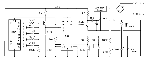
build varying brightness ac lamp circuit
A varying brightness AC lamp circuit utilizes a silicon-controlled rectifier (SCR) to gradually adjust the intensity of a 120-volt light bulb by controlling the duration of AC line voltage applied to the lamp during each half cycle. The circuit is...

Three-Power-Level Triac Controller Circuit
Three power levels are provided by the two logic inputs of this enhanced circuit. R5, D4, D5, and O2 create a power supply for the logic integrated circuit. These components can be excluded if an alternative low voltage source is...
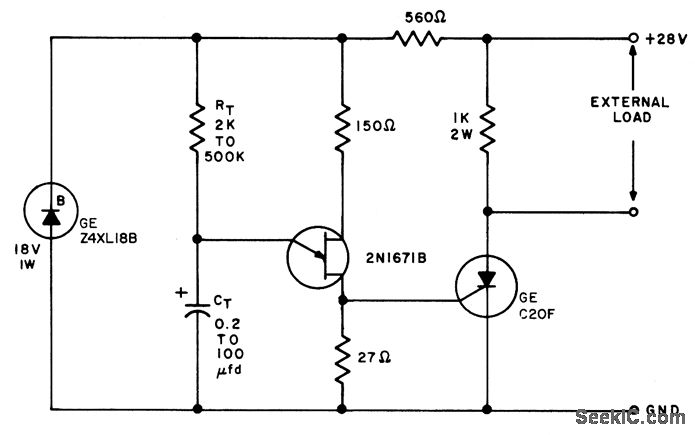
SCR UJI TIME DELAY
The timing interval is initiated by applying power and is determined by the resistor-capacitor (RT-CT) combination. At the end of the interval, a unijunction transistor triggers a silicon controlled rectifier (SCR) to apply nearly the full supply voltage to the...
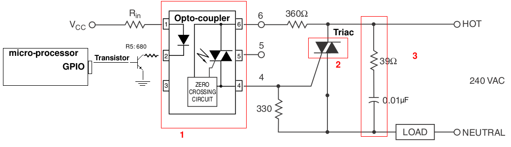
ac TRIAC dimmer circuit design help (resistive load)
A light-dimming control system is being developed for a 240V heat lamp with a power dissipation of approximately 250W. The objective is to adjust the heat output of the lamp using control from a microprocessor. The development is based on...
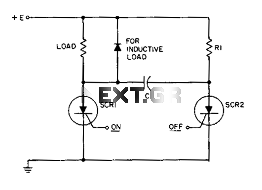
Dc static switch
This circuit is a static SCR switch designed for use in a DC circuit. When a low-power signal is applied to the gate of SCR1, this SCR is triggered, allowing voltage to be applied to the load. The right plate...
Simple Lamp Dimmer Fan Regulator
The circuit operates by adjusting the firing angle of the Triac. Resistors R1, R2, and capacitor C2 are involved in this process. The firing angle can be modified by changing the value of any of these components, with R1 designated...