


Tubular xenon lamp circuit
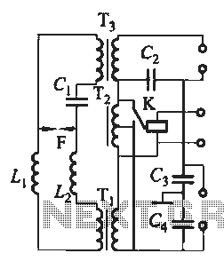
Description: Tubular xenon lamp power, high brightness, known as the "little sun." Tubular xenon lamp wiring is illustrated in Figure 2-6.
The tubular xenon lamp is a high-intensity discharge (HID) light source, characterized by its ability to produce a bright white light that closely resembles natural sunlight. This lamp operates by ionizing xenon gas within a glass tube, leading to the emission of light when an electrical current passes through the gas. The design of the lamp typically includes a tubular shape to maximize the surface area for light emission and to facilitate effective heat dissipation.
The wiring configuration for a tubular xenon lamp involves several key components. The lamp is connected to a high-voltage power supply, which is essential for initiating the ionization process. This power supply usually incorporates a ballast to regulate the current flowing through the lamp, ensuring stable operation and preventing damage due to fluctuations in voltage.
In a typical circuit schematic for a tubular xenon lamp, the following elements are present:
1. **Power Supply**: A high-voltage source, often in the range of several kilovolts, is necessary for starting the lamp. This power supply may include a transformer to step up the voltage and a rectifier to convert AC to DC if required.
2. **Ballast**: A ballast is employed to limit the current once the lamp is ignited. This component can be an electromagnetic or electronic ballast, depending on the design requirements. The ballast ensures that the lamp operates within its specified current range, optimizing performance and longevity.
3. **Ignitor**: An ignitor may be included in the circuit to provide a high-voltage pulse that helps initiate the arc within the xenon gas. This component is crucial for starting the lamp and is typically activated momentarily during the ignition phase.
4. **Lamp Socket**: The lamp is mounted in a socket that provides electrical connections to the power supply and ballast. This socket must be designed to withstand the high temperatures generated during operation.
5. **Cooling Mechanism**: Due to the high brightness and heat generated by the lamp, a cooling mechanism, such as a fan or heat sink, may be integrated into the design to prevent overheating and ensure consistent performance.
The schematic diagram referenced as Figure 2-6 would illustrate these components and their interconnections, providing a visual guide for proper wiring and assembly of the tubular xenon lamp circuit. The arrangement of components should be designed to minimize electromagnetic interference and ensure safety during operation. Proper insulation and protective casing are also essential to safeguard against electrical hazards.Tubular Xe lamp power, high brightness, known as the "little sun." Tubular xenon lamp wiring shown in Figure 2-6.
The tubular xenon lamp is a high-intensity discharge (HID) light source, characterized by its ability to produce a bright white light that closely resembles natural sunlight. This lamp operates by ionizing xenon gas within a glass tube, leading to the emission of light when an electrical current passes through the gas. The design of the lamp typically includes a tubular shape to maximize the surface area for light emission and to facilitate effective heat dissipation.
The wiring configuration for a tubular xenon lamp involves several key components. The lamp is connected to a high-voltage power supply, which is essential for initiating the ionization process. This power supply usually incorporates a ballast to regulate the current flowing through the lamp, ensuring stable operation and preventing damage due to fluctuations in voltage.
In a typical circuit schematic for a tubular xenon lamp, the following elements are present:
1. **Power Supply**: A high-voltage source, often in the range of several kilovolts, is necessary for starting the lamp. This power supply may include a transformer to step up the voltage and a rectifier to convert AC to DC if required.
2. **Ballast**: A ballast is employed to limit the current once the lamp is ignited. This component can be an electromagnetic or electronic ballast, depending on the design requirements. The ballast ensures that the lamp operates within its specified current range, optimizing performance and longevity.
3. **Ignitor**: An ignitor may be included in the circuit to provide a high-voltage pulse that helps initiate the arc within the xenon gas. This component is crucial for starting the lamp and is typically activated momentarily during the ignition phase.
4. **Lamp Socket**: The lamp is mounted in a socket that provides electrical connections to the power supply and ballast. This socket must be designed to withstand the high temperatures generated during operation.
5. **Cooling Mechanism**: Due to the high brightness and heat generated by the lamp, a cooling mechanism, such as a fan or heat sink, may be integrated into the design to prevent overheating and ensure consistent performance.
The schematic diagram referenced as Figure 2-6 would illustrate these components and their interconnections, providing a visual guide for proper wiring and assembly of the tubular xenon lamp circuit. The arrangement of components should be designed to minimize electromagnetic interference and ensure safety during operation. Proper insulation and protective casing are also essential to safeguard against electrical hazards.Tubular Xe lamp power, high brightness, known as the "little sun." Tubular xenon lamp wiring shown in Figure 2-6.
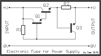
Auto Fuse for power supply
The power supply, with electronic stabilization - mainly those of laboratories - should be protected from overcurrent that emanates from short-circuits, erroneous association, or damage of repaired appliances. The circuit offers effective protection in power supply with output voltage up...
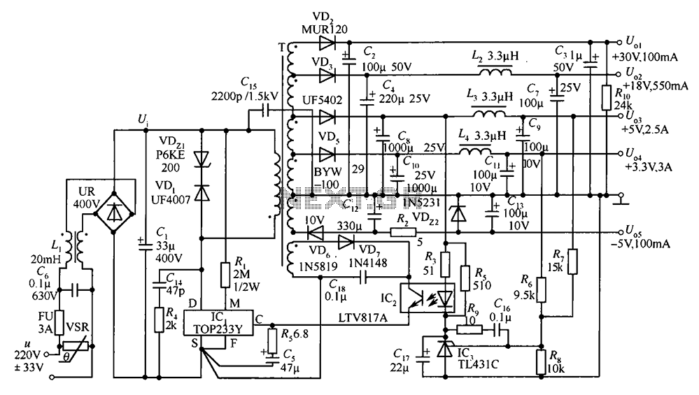
35W switching power supply circuit having a set-top box output of 5
A 35W switching power supply circuit designed for a set-top box output is depicted in Figure 5. It features five distinct voltage outputs: Uo1 (+30V, 100mA), Uo2 (+18V, 550mA), Uo3 (+5V, 2.5A), Uo4 (+3.3V, 3A), and Uo5 (-5V, 100mA). The...

symmetric 12v to 5v converter
Symmetric 12V to 5V converter power supply. Refer to the designated page for an explanation regarding the associated circuit diagram.
The symmetric 12V to 5V converter power supply is designed to efficiently step down a 12V input voltage to a regulated...
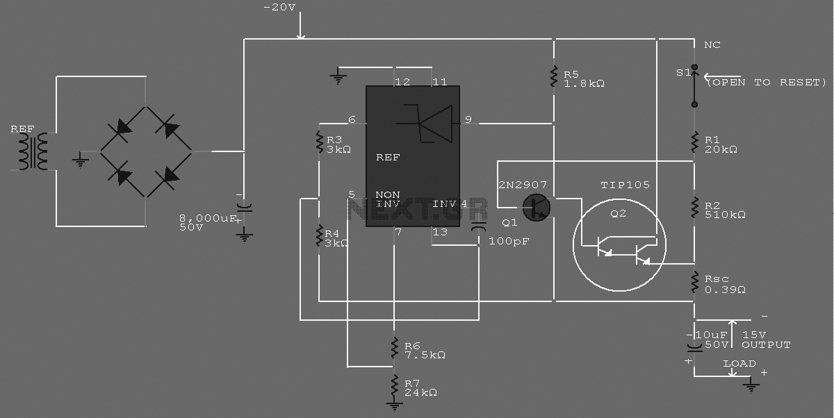
-15 V 1-A Regulated Power Supply
The supply receives -20 V from the rectifier/filter which is fed to the collector of the Darlington pnp pass transistor, a TIP105. The base drive to the TIP105 is supplied through resistor R5. The base of the TIP is driven...
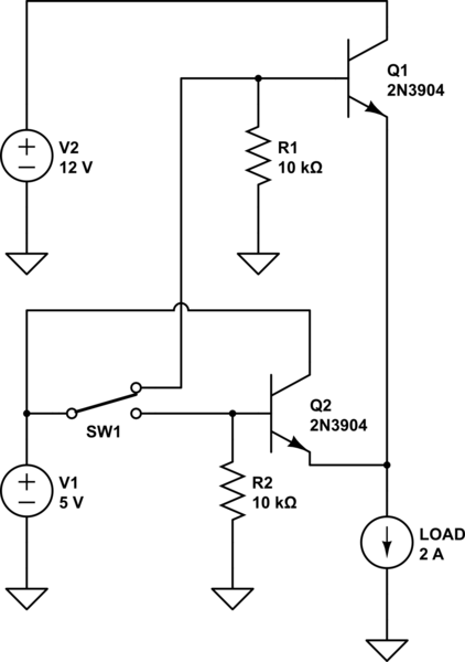
power How can I switch a high current with a low-rated switch
The project involves designing and constructing a breadboard power supply that draws power from an ATX-like switch-mode power supply (SMPS) using a 4-pin Molex connector. The design features a switch to select either a 12V or 5V output. However, the...
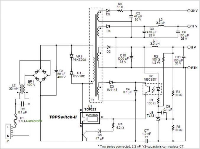
Designing Multiple Output Power Supplies With Topswitch
This application note describes a digital blood pressure meter concept that utilizes integrated pressure sensor analog signal-conditioning circuitry, microcontroller hardware/software, and a liquid crystal display. The sensing system measures cuff pressure (CP) and extracts pulses for analysis to determine systolic...
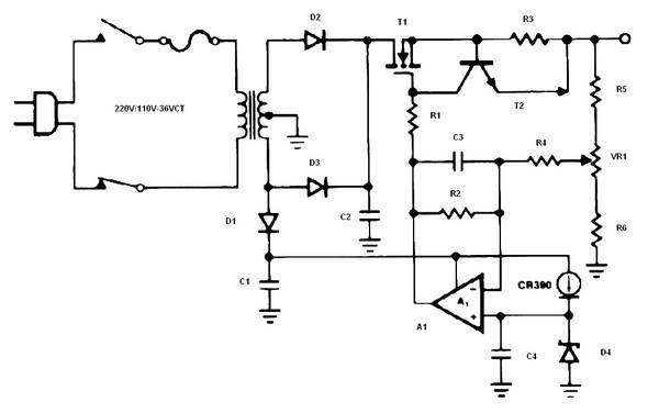
Battery charger or Power Supply 14 volt 4 ampere
The schematic diagram originates from a circuit designed as a battery charger/power supply with an output of 14V and a maximum current of 4A, utilizing the VN64GA MOSFET. This high-performance battery charger is specifically engineered for gelled electrolyte lead-acid batteries,...
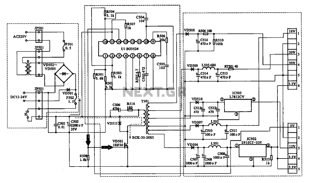
Changhong DVB-2000 digital satellite receiver switching power supply circuit
The Changhong DVB-2000 digital satellite receiver features a switching power supply circuit. This circuit primarily comprises a power input section, an oscillation switching circuit, and a DC output section. The power input circuit receives 22V AC from a step-down transformer,...
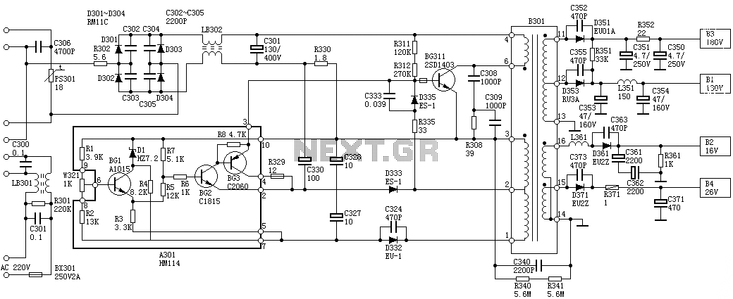
Sanyo 83P switching power supply circuit diagram
Oscillation: The positive terminal voltage of C310 is approximately 300V. The resistors R311 and R312 are connected to the switch BG311 at the B pole, while the B301 winding via the switching transformer (4) and (6) is connected to the...