


TWH9104 holiday lights ASIC
#holiday lights
#ASIC
#220V AC
#bridge rectifier
#full-wave
#buck regulator
#filtered output
#LED
#lamp
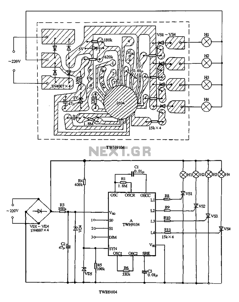
Description: The circuit utilizes a VDI-VD4 bridge rectifier to convert 220V AC into a full-wave pulsating voltage, which powers lights H1 to H4. A buck regulator, composed of resistor R3 and diode VD4, reduces this voltage to approximately 5V DC, which is used for the manifold A electricity supply. The manifold features four output terminals, Ll to LA, connected to the gate of a thyristor through resistors R8 and RIl, allowing control over their conduction angle. This enables the lights H1 to H4 to flash according to demand. The oscillation rate can be adjusted via external resistor R6 connected to OSC2, affecting the dimming rate of the light strings. The chase rate of the lantern string is determined by resistors Rl and Cl; for example, a potentiometer Rl of 2.2MΩ in series with a fixed 510kΩ resistor allows for adjustment of the chase rate. Mood lighting effects are controlled through switches SI and DIM, which enable users to select different flashing levels by connecting short wires to the chip pads labeled 1, 2, and 3, as well as the + and - contact pads. This configuration allows for a variety of lighting effects to be achieved through simple modifications.
The circuit operates by first converting the 220V AC input into a full-wave pulsating voltage using the VDI-VD4 bridge rectifier. This rectification process is essential for providing a stable DC voltage to power the subsequent components. The output from the rectifier is then processed by a buck regulator, which steps down the voltage to approximately 5V DC. This lower voltage is crucial for the operation of the manifold A, which distributes power to the connected lights and components.
The thyristor gate control, achieved through resistors R8 and RIl, allows for precise manipulation of the conduction angle. By adjusting this angle, the intensity and flashing behavior of lights H1 to H4 can be tailored to meet specific requirements. This feature is particularly useful in applications where dynamic lighting effects are desired.
The circuit also includes an oscillation control mechanism, where the external resistor R6 influences the dimming characteristics of the lights. The ability to modify the dimming rate provides flexibility in creating different lighting moods, which can be particularly advantageous in decorative or atmospheric lighting applications.
Additionally, the chase rate of the lantern string is determined by the combination of resistors Rl and Cl. The use of a potentiometer allows for real-time adjustments, enabling users to customize the speed at which the lights chase. This can enhance the visual appeal of the lighting setup, making it suitable for various events or decorative purposes.
The mood lighting functionality is further enhanced by the inclusion of switches SI and DIM. These switches allow users to select from different flashing levels, providing an easy interface for changing lighting effects. By connecting short wires to the designated chip pads, users can effortlessly switch between various configurations, enabling a wide range of creative lighting options.
In summary, this circuit design offers a versatile and adjustable lighting solution that can be tailored for various applications, combining efficient power conversion, dynamic control, and user-friendly interfaces to achieve desired lighting effects.220V AC by the VDI-VD4 bridge rectifier to produce a full-wave pulsating voltage electricity for lights H1 ~ H4, the other side by R3 and VD4 buck regulator, C2 filtered output of about 5v DC voltage used for the manifold A Electricity. Manifold four output terminals Ll-LA by R8-RIl added thyristor gate, in order to change their conduction angle, so that lights H1-H4 according to need flash. Changes in OSCI, external oscillation resistor R6 resistance OSC2 can change the rate of dimming lights string.
Lantern string chase rate by Rl and Cl decisions, such as the potentiometer Rl to 2.2Mo series again a 510k o fixed resistor, adjust the potentiometer can adjust lantern string chase rate. Mood lights flashing by so, SI and DIM end (ie 1-3 determine the level of end) level, according to their needs reader with a short wire to l on a chip, 2, 3 pads and + ,.
contact pads can also be used in three lx2 small switch so, Sl, DIM side between VDD, vss be cut change in the composition of many tricks lantern controller.
The circuit operates by first converting the 220V AC input into a full-wave pulsating voltage using the VDI-VD4 bridge rectifier. This rectification process is essential for providing a stable DC voltage to power the subsequent components. The output from the rectifier is then processed by a buck regulator, which steps down the voltage to approximately 5V DC. This lower voltage is crucial for the operation of the manifold A, which distributes power to the connected lights and components.
The thyristor gate control, achieved through resistors R8 and RIl, allows for precise manipulation of the conduction angle. By adjusting this angle, the intensity and flashing behavior of lights H1 to H4 can be tailored to meet specific requirements. This feature is particularly useful in applications where dynamic lighting effects are desired.
The circuit also includes an oscillation control mechanism, where the external resistor R6 influences the dimming characteristics of the lights. The ability to modify the dimming rate provides flexibility in creating different lighting moods, which can be particularly advantageous in decorative or atmospheric lighting applications.
Additionally, the chase rate of the lantern string is determined by the combination of resistors Rl and Cl. The use of a potentiometer allows for real-time adjustments, enabling users to customize the speed at which the lights chase. This can enhance the visual appeal of the lighting setup, making it suitable for various events or decorative purposes.
The mood lighting functionality is further enhanced by the inclusion of switches SI and DIM. These switches allow users to select from different flashing levels, providing an easy interface for changing lighting effects. By connecting short wires to the designated chip pads, users can effortlessly switch between various configurations, enabling a wide range of creative lighting options.
In summary, this circuit design offers a versatile and adjustable lighting solution that can be tailored for various applications, combining efficient power conversion, dynamic control, and user-friendly interfaces to achieve desired lighting effects.220V AC by the VDI-VD4 bridge rectifier to produce a full-wave pulsating voltage electricity for lights H1 ~ H4, the other side by R3 and VD4 buck regulator, C2 filtered output of about 5v DC voltage used for the manifold A Electricity. Manifold four output terminals Ll-LA by R8-RIl added thyristor gate, in order to change their conduction angle, so that lights H1-H4 according to need flash. Changes in OSCI, external oscillation resistor R6 resistance OSC2 can change the rate of dimming lights string.
Lantern string chase rate by Rl and Cl decisions, such as the potentiometer Rl to 2.2Mo series again a 510k o fixed resistor, adjust the potentiometer can adjust lantern string chase rate. Mood lights flashing by so, SI and DIM end (ie 1-3 determine the level of end) level, according to their needs reader with a short wire to l on a chip, 2, 3 pads and + ,.
contact pads can also be used in three lx2 small switch so, Sl, DIM side between VDD, vss be cut change in the composition of many tricks lantern controller.
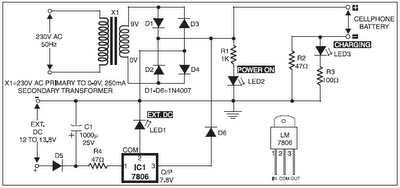
mobile phone battery charger circuit
The 220V AC mains supply is downconverted to 9V AC by transformer X1. The transformer output is rectified by diodes D1 through D4 wired in bridge configuration, and the positive DC supply is directly connected to the charger's output contact,...
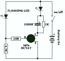
Led Flasher with a BC547 NPN transistor
This is a novel flasher circuit using a single driver transistor that takes its flash-rate from a flashing LED. The flasher in the photo is 3mm. An ordinary LED will not work. The flash rate cannot be altered by the...
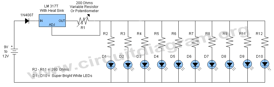
led dimmer circuit
This schematic illustrates a simple yet effective LED dimmer circuit utilizing the well-known voltage regulator IC LM317T. The LM317T can function as a current regulator, as demonstrated in this circuit. It features ten super bright white LEDs, although the quantity...
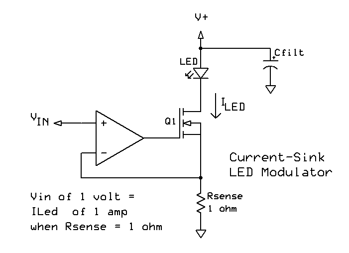
LED high power modulator
More:
An electronic schematic is a representation of the components and connections within an electronic circuit. It serves as a blueprint for constructing electronic devices, allowing engineers and technicians to visualize how components interact and function together.
The schematic typically...
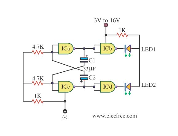
The simple LED Flasher by IC 4011
This is simply a LED flasher circuit that is suggested for construction. However, it is important to understand the use of transistors, which can be challenging when learning about digital electronics.
The LED flasher circuit operates by utilizing a basic astable...
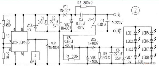
Light control automatic energy-saving LED lights circuit
The circuit is depicted in Figure 1, while the electrical schematic diagram is presented in Figure 2. The AC voltage of 220V is reduced by components C3 and R3. The diodes VD1 and VD2 rectify the voltage, and capacitors C2...

putting a led instead of an incandescent bulb on my bike
A few days ago, the rear light burned out. While it is not critical, the front light is essential for nighttime visibility. The reflective red plastic at the back provides some safety, so there is no immediate concern. Nonetheless, a...
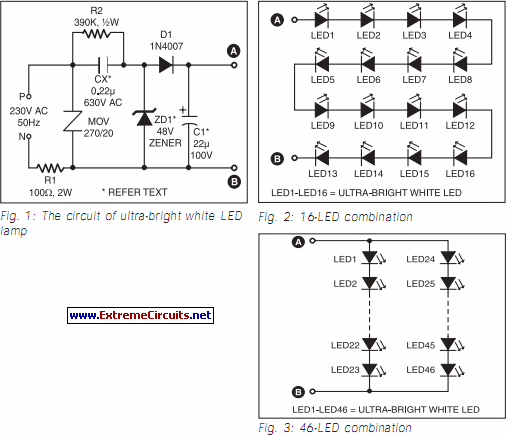
Ultra Bright LED Lamp circuit
This ultra-bright white LED lamp operates on 230V AC with low power consumption. It is suitable for illuminating VU meters, SWR meters, and similar applications. The ultra-bright LEDs available in the market range from Rs 8 to 15. These LEDs...
temporary led lampilluminator circuit
Here is a design for a temporary lamp circuit that is very helpful in emergency situations or in any application where there is limited time to turn off the lamp. Simply press the push button to perform a quick task,...