


Use TWH8751 street light control circuit
#TWH8751
#automatic control
#street light
#power switch
#light sensor
#power supply
#integrated circuit
#energy saving
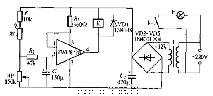
Description: Automatic lights using a light sensor, the TWH87SL power switch integrated circuit consists of a first input terminal TWH8751 connected to the positive terminal of the power supply. The output pin state is determined by the strobe terminal, which is electrically connected to the control level. During the day, the RP resistor exhibits low resistance due to natural light, causing the strobe terminal to be high. Consequently, the output terminal is high, and the relay K does not activate, keeping the lights E off. At night, the light exposure causes the RP to exhibit high electrical resistance, resulting in a low strobe terminal. This activates the internal Darlington transistor in the TWH8751, bringing the pin low, which pulls in the relay K and closes its contacts, powering the lights E. The sensitivity of the light control circuit can be adjusted by varying the resistance of RP. Additionally, a pulse interference absorption circuit, represented by R and C, can mitigate the impact of ambient nighttime light on the circuit's operation. The circuit operates with a 220V input, utilizing a small, high-quality 121 jVA power transformer. The appropriate load size for relay K should be selected based on the operating voltage of 12V, such as the JZ (22F, DC12V) type.
The automatic lighting circuit described integrates a light-sensitive control mechanism using the TWH87SL power switch integrated circuit. The primary function of this circuit is to automatically turn on lights in response to ambient light conditions. The TWH8751 input terminal receives power from a designated supply, and the operation of the circuit hinges on the relationship between the light sensor and the relay.
During daylight hours, the RP resistor's low resistance allows the strobe terminal to maintain a high state, which prevents the relay K from activating. This ensures that the lights remain off, conserving energy and enhancing safety by avoiding unnecessary illumination. Conversely, in low-light conditions, the RP resistor's resistance increases, resulting in a low signal at the strobe terminal. This triggers the TWH8751's internal Darlington transistor, which in turn activates relay K. The closure of relay K's contacts enables the flow of current to the lights E, illuminating the area as required.
The circuit's sensitivity to light can be finely tuned by adjusting the RP resistor, allowing for customization based on specific environmental conditions or user preferences. The inclusion of a pulse interference absorption circuit, consisting of resistors R and capacitors C, serves to filter out any transient signals that may cause false triggering of the relay due to fluctuations in ambient light levels.
Powering the circuit with a 220V AC supply necessitates the use of a compact, high-efficiency transformer rated at 121 jVA, which steps down the voltage to a manageable level for the relay and associated components. When selecting relay K, it is crucial to ensure compatibility with a 12V operating voltage, with options such as the JZ (22F, DC12V) relay being suitable for this application. This design offers a reliable and efficient solution for automatic lighting control in various settings, enhancing convenience and energy efficiency. Automatic lights using a light twist, it TWH87sl power switch integrated circuit composed of a first input terminal TWH8751 O feet to the positive terminal of the power supply, the output pin state by the end strobe terminal that is electrically feet first level control. During the day, RP by natural light exhibits low resistance, strobe terminal feet high, so the output terminal feet high, the relay K is not action, not bright lights E. Night, Rl. Light exposure exhibits high electrical resistance, strobe terminal feet low, TWH8751 internal Darlington turned, pin is low, the relay K pull its station close contacts kl, powered lights E light.
Adjusting the resistance of RP can adjust the sensitivity of the light control circuit. R., C. A pulse interference absorption circuit, can eliminate amidine nighttime light on the impact short circuit. T bite Chuan 220V: 121:, jVA small, high quality power transformer. K blood select the appropriate load size I according to operating voltage of 12V relay, such as JZ ( 22F, DC12V type.
The automatic lighting circuit described integrates a light-sensitive control mechanism using the TWH87SL power switch integrated circuit. The primary function of this circuit is to automatically turn on lights in response to ambient light conditions. The TWH8751 input terminal receives power from a designated supply, and the operation of the circuit hinges on the relationship between the light sensor and the relay.
During daylight hours, the RP resistor's low resistance allows the strobe terminal to maintain a high state, which prevents the relay K from activating. This ensures that the lights remain off, conserving energy and enhancing safety by avoiding unnecessary illumination. Conversely, in low-light conditions, the RP resistor's resistance increases, resulting in a low signal at the strobe terminal. This triggers the TWH8751's internal Darlington transistor, which in turn activates relay K. The closure of relay K's contacts enables the flow of current to the lights E, illuminating the area as required.
The circuit's sensitivity to light can be finely tuned by adjusting the RP resistor, allowing for customization based on specific environmental conditions or user preferences. The inclusion of a pulse interference absorption circuit, consisting of resistors R and capacitors C, serves to filter out any transient signals that may cause false triggering of the relay due to fluctuations in ambient light levels.
Powering the circuit with a 220V AC supply necessitates the use of a compact, high-efficiency transformer rated at 121 jVA, which steps down the voltage to a manageable level for the relay and associated components. When selecting relay K, it is crucial to ensure compatibility with a 12V operating voltage, with options such as the JZ (22F, DC12V) relay being suitable for this application. This design offers a reliable and efficient solution for automatic lighting control in various settings, enhancing convenience and energy efficiency. Automatic lights using a light twist, it TWH87sl power switch integrated circuit composed of a first input terminal TWH8751 O feet to the positive terminal of the power supply, the output pin state by the end strobe terminal that is electrically feet first level control. During the day, RP by natural light exhibits low resistance, strobe terminal feet high, so the output terminal feet high, the relay K is not action, not bright lights E. Night, Rl. Light exposure exhibits high electrical resistance, strobe terminal feet low, TWH8751 internal Darlington turned, pin is low, the relay K pull its station close contacts kl, powered lights E light.
Adjusting the resistance of RP can adjust the sensitivity of the light control circuit. R., C. A pulse interference absorption circuit, can eliminate amidine nighttime light on the impact short circuit. T bite Chuan 220V: 121:, jVA small, high quality power transformer. K blood select the appropriate load size I according to operating voltage of 12V relay, such as JZ ( 22F, DC12V type.
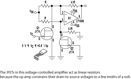
Flyback Power Supply Powers Subscriber Line Interface Circuit
Cable and xDSL modems are increasingly popular, leading to a need for designs that interface with existing telephones at subscriber locations. The subscriber line interface circuit (SLIC) within the modem must ring the phone and provide loop current during conversations....
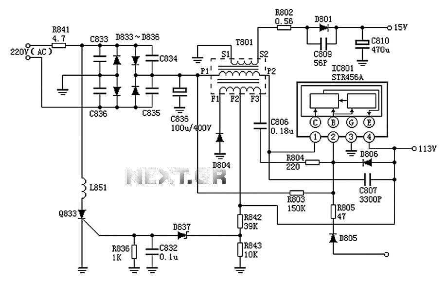
Panasonic M12H switching power supply circuit diagram
The Panasonic M12H switching power supply circuit is utilized in Panasonic models such as TC-230H, TC-2030DHN, TC-830D, and TC-840D. The circuit operates with an oscillation frequency that generates approximately 300V DC voltage at C836. The T801 transformer is involved in...
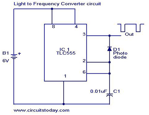
Light to Frequency converter
A simple light-to-frequency converter circuit with a diagram and schematic. It is used as a light intensity measurement circuit. The design utilizes the TLC555, a CMOS version of the NE555 timer IC.
The light-to-frequency converter circuit is designed to convert varying...
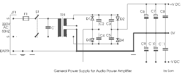
Power Supply for P.A. Class40
For its maximum result, the final stage of the amplifier should have the proper power supply, as the flowing currents are very high. A Class A amplifier requires attention. These are the rules for the power supply for the Class...
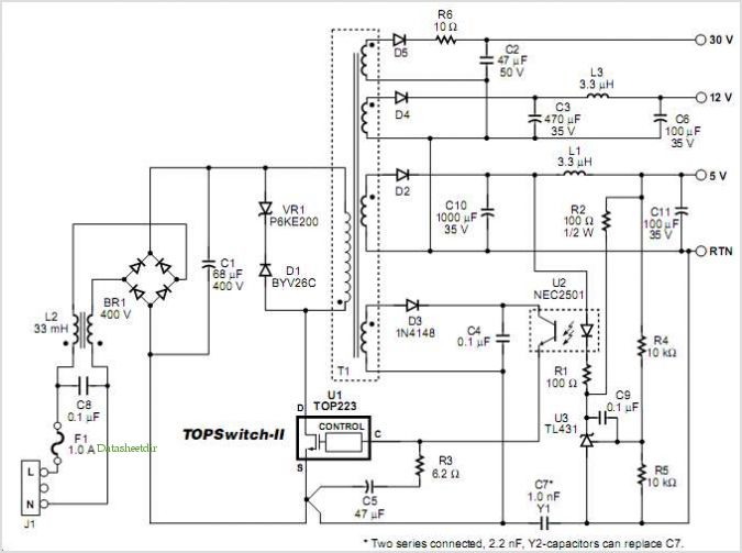
Designing Multiple Output Power Supplies With Topswitch
This application note describes a digital blood pressure meter concept that utilizes integrated pressure sensor analog signal-conditioning circuitry, microcontroller hardware/software, and a liquid crystal display. The sensing system measures cuff pressure (CP) and extracts pulses for analysis to determine systolic...
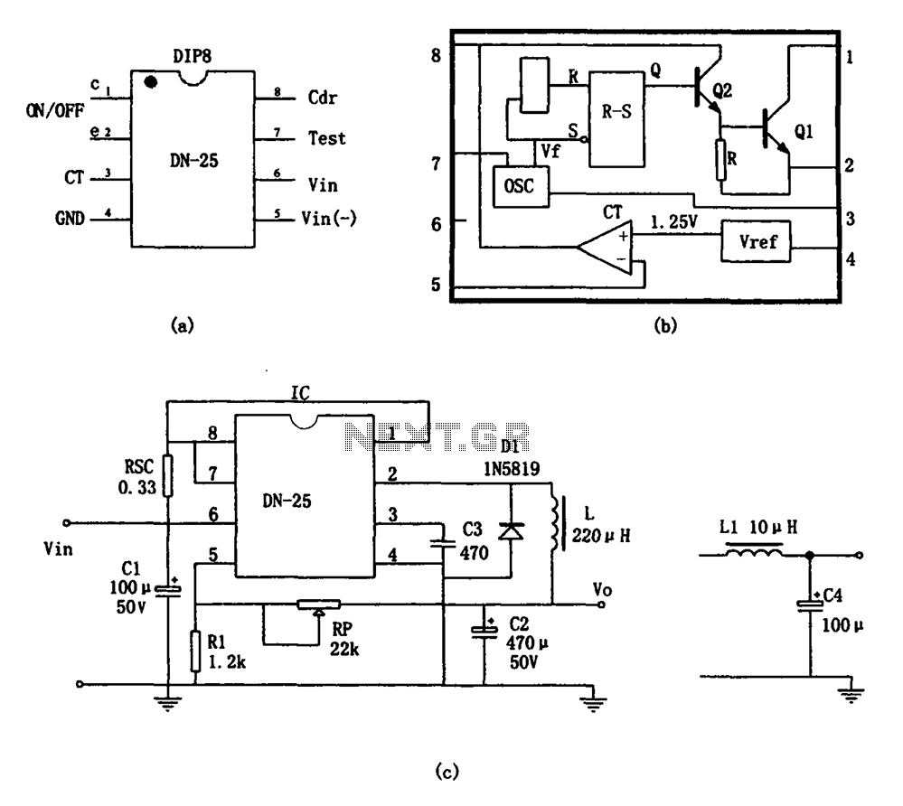
Switching power supply monolithic switching regulator DN-25 configuration
As shown in the figure, the DN-25 IC is a switching power supply. The DN-25 is a monolithic switching power supply device suitable for medium output current applications and a wide voltage range. Its main performance indicators include an input...
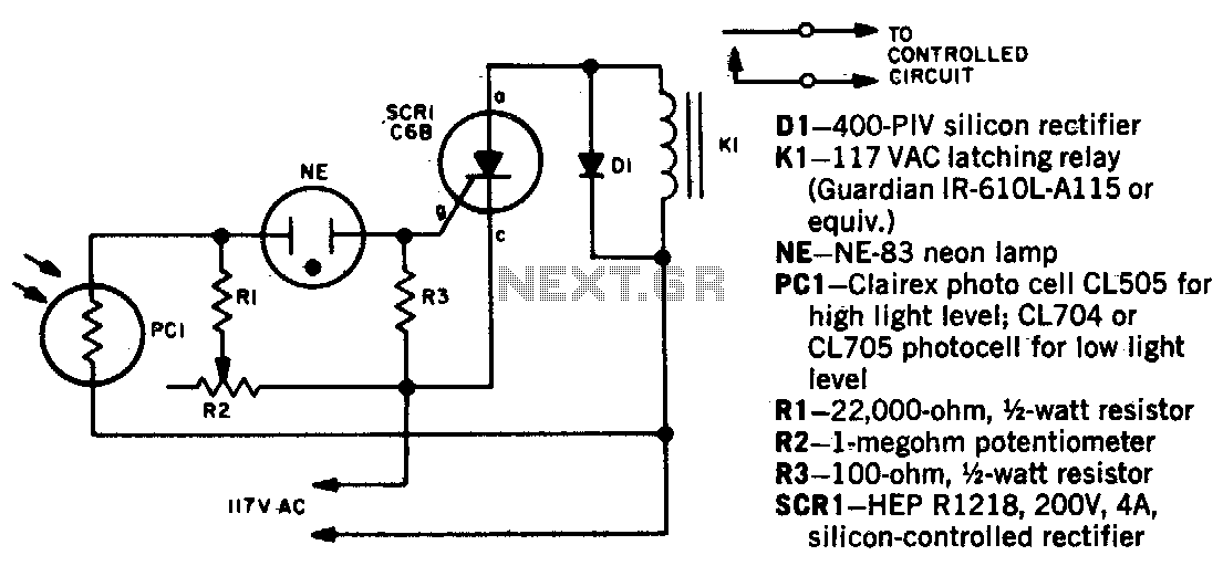
Light beam operated on-off relay
When a beam of light strikes the photocell, the voltage across the neon lamp NE-1 rises sharply. NE-1 turns on and triggers the SCR. K1 is an impulse relay whose contacts remain in position even after the coil current is...
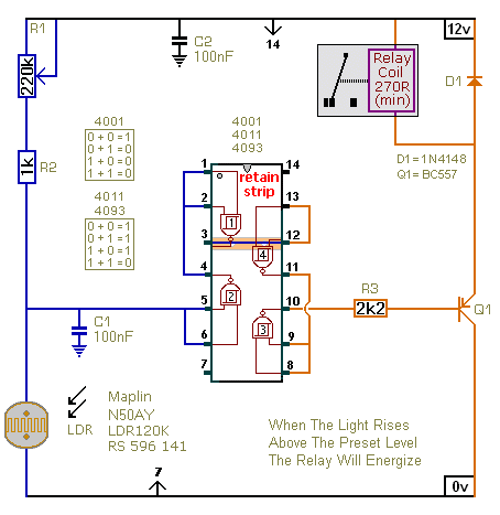
Light Controlled Relays
The first circuit energizes the relay when the light rises above the preset level. The second circuit energizes the relay when the light falls below the preset level. The two circuits are practically identical. The only difference between them is...
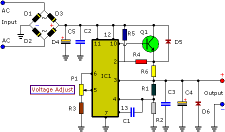
3-30V 3A Adjustable Regulated DC Power Supply
This power supply is designed as either an auxiliary or a permanent power source for various circuits that require a stabilized DC voltage ranging from 3 to 30V, with a maximum current consumption of 3A. Additionally, this power supply unit...